00197498-03_UM_SiplaceCA-Serie_EN.pdf - 第308页
5 Setting up and Commissioning User Manual SIPLACE CA-Series 5.5 Setting Up the Placement Machine From software version SC.708.0 Edition 12/2014 EN -DR AFT 308 5.5.10.7 Install i ng the Bottom Hand Guard The CA-Series pl…
User Manual SIPLACE CA-Series 5 Setting up and Commissioning
From software version SC.708.0 Edition 12/2014 EN -DRAFT 5.5 Setting Up the Placement Machine
307
5.5.10.5 Fitting the Ground Cable for the Doors
Fasten the two ground cables for the doors (item 4 in fig. 5.5 - 14) to the machine frame as
follows:
5
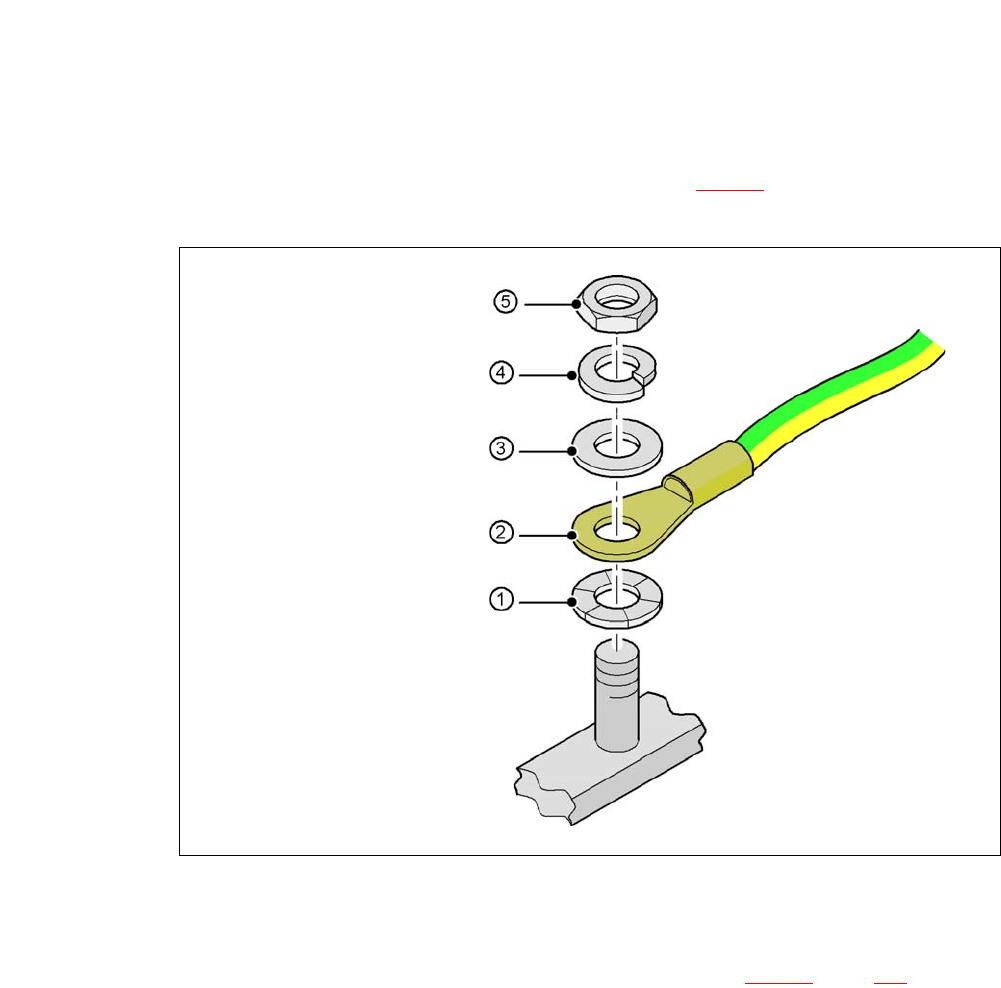
Fig. 5.5 - 16 Fitting the ground cable
5.5.10.6 Checking and Setting the Protective Cover Switch
Check the function of the protective cover switch (item 7 in fig. 5.5 - 15, page 294).
Adjust the protective cover switch if necessary (see service manual).
5
Hex nut M
Spring washer M, DIN 7980
Washer M, DIN 125
Cable lug, annular
Contact washer
5 Setting up and Commissioning User Manual SIPLACE CA-Series
5.5 Setting Up the Placement Machine From software version SC.708.0 Edition 12/2014 EN -DRAFT
308
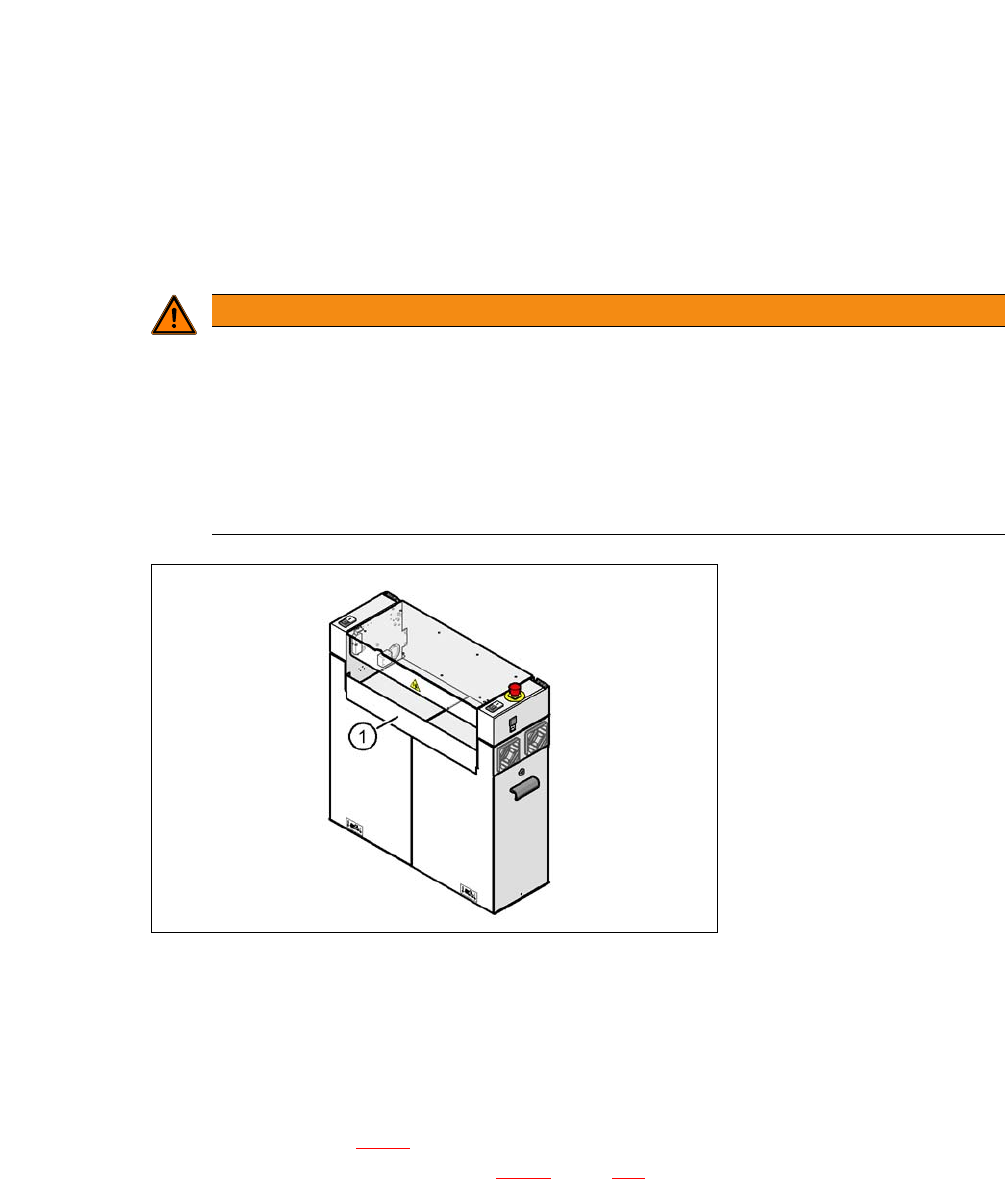
5.5.10.7 Installing the Bottom Hand Guard
The CA-Series placement machines are only supplied with one "bottom" hand guard. However, if
the placement machines are installed in a line, there will be no hand guard between neighboring
output and input conveyors.
5
5
Fig. 5.5 - 17 Fitting the "bottom" hand guard on the PCB input side
(1) "Bottom" hand guard [03003432-01]
5.5.11 Installing the Box PC Unit on the CA4 i
The SIPLACE CA-Series placement machines can be fitted once with the box PC unit or with a
computer unit. Section 5.5.11
describes installation of the box PC. For a description of how to in-
stall the computer unit, refer to section 5.5.12
, page 314.
WARNING
Unauthorized access by personnel!
A missing hand guard between the input and output sides of the placement machine in a
production line could lead to unauthorized access if staff reach into the inside of the place-
ment machine.
Always fit the bottom hand guard at the input side of the first placement machine and
on the output side of the last placement machine in a line [03003432-01] with 4 hexa-
gon socket-head screws M4x12.
User Manual SIPLACE CA-Series 5 Setting up and Commissioning
From software version SC.708.0 Edition 12/2014 EN -DRAFT 5.5 Setting Up the Placement Machine
309
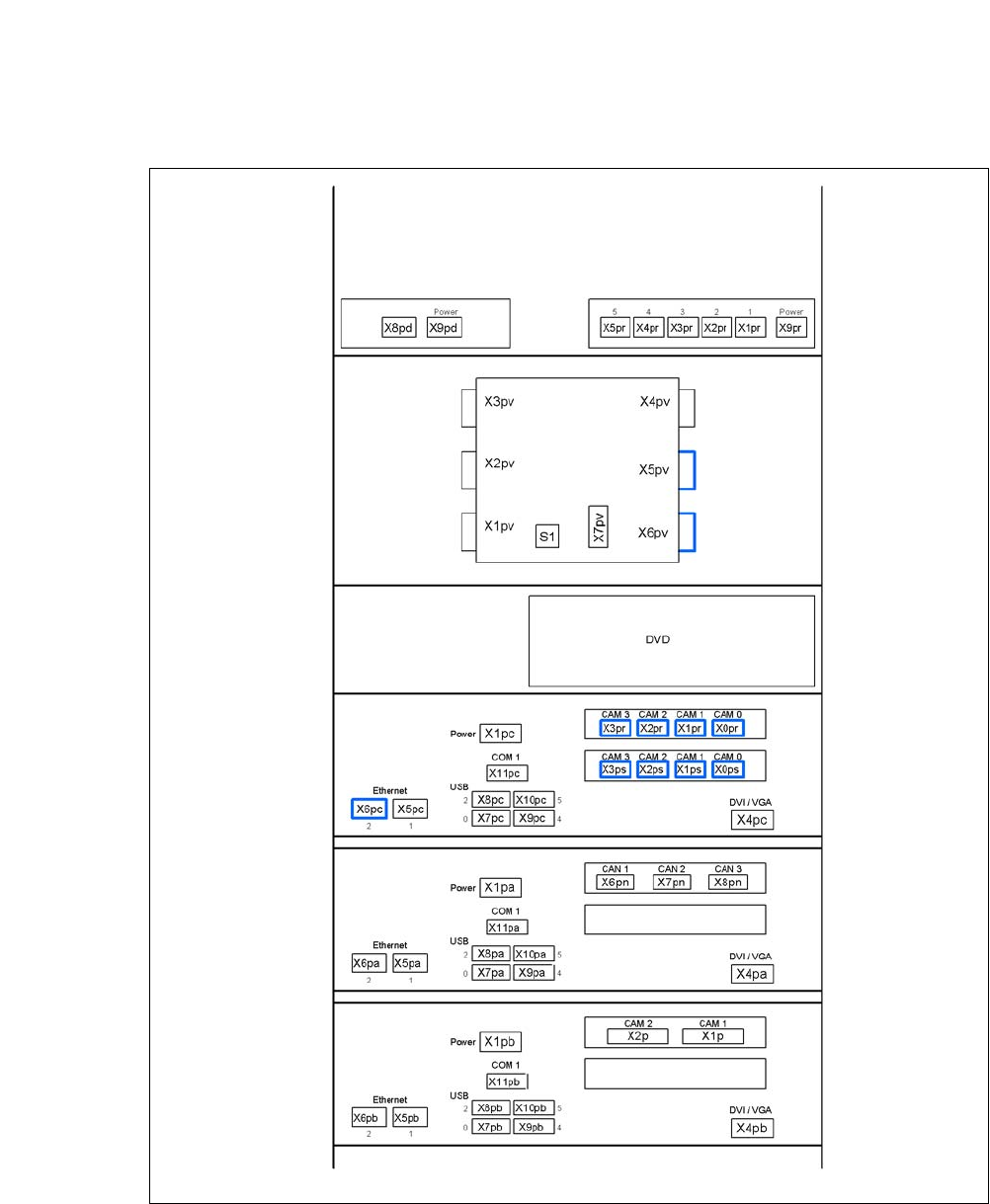
5.5.11.1 Box PC Unit - Electrical Connection Points
5
Fig. 5.5 - 18 Box PC unit, front - connecting the plug
USB hub
Ethernet switch
(3D sensor option)
Video multiplexer
Control computer
Machine controller
3D sensor computer option