00197498-03_UM_SiplaceCA-Serie_EN.pdf - 第138页
3 Technical Data User Manual SIPLACE CA-Series 3.4 Dimensions and Weight of the SIPLACE CA From software version SC.708.0 Edition 12/2014 EN -DRAFT 138 3.4.7 Center of Gravity for CA-Se ries Machines 3 Fig. 3.4 - 9 Cente…
User Manual SIPLACE CA-Series 3 Technical Data
From software version SC.708.0 Edition 12/2014 EN -DRAFT 3.4 Dimensions and Weight of the SIPLACE CA
137
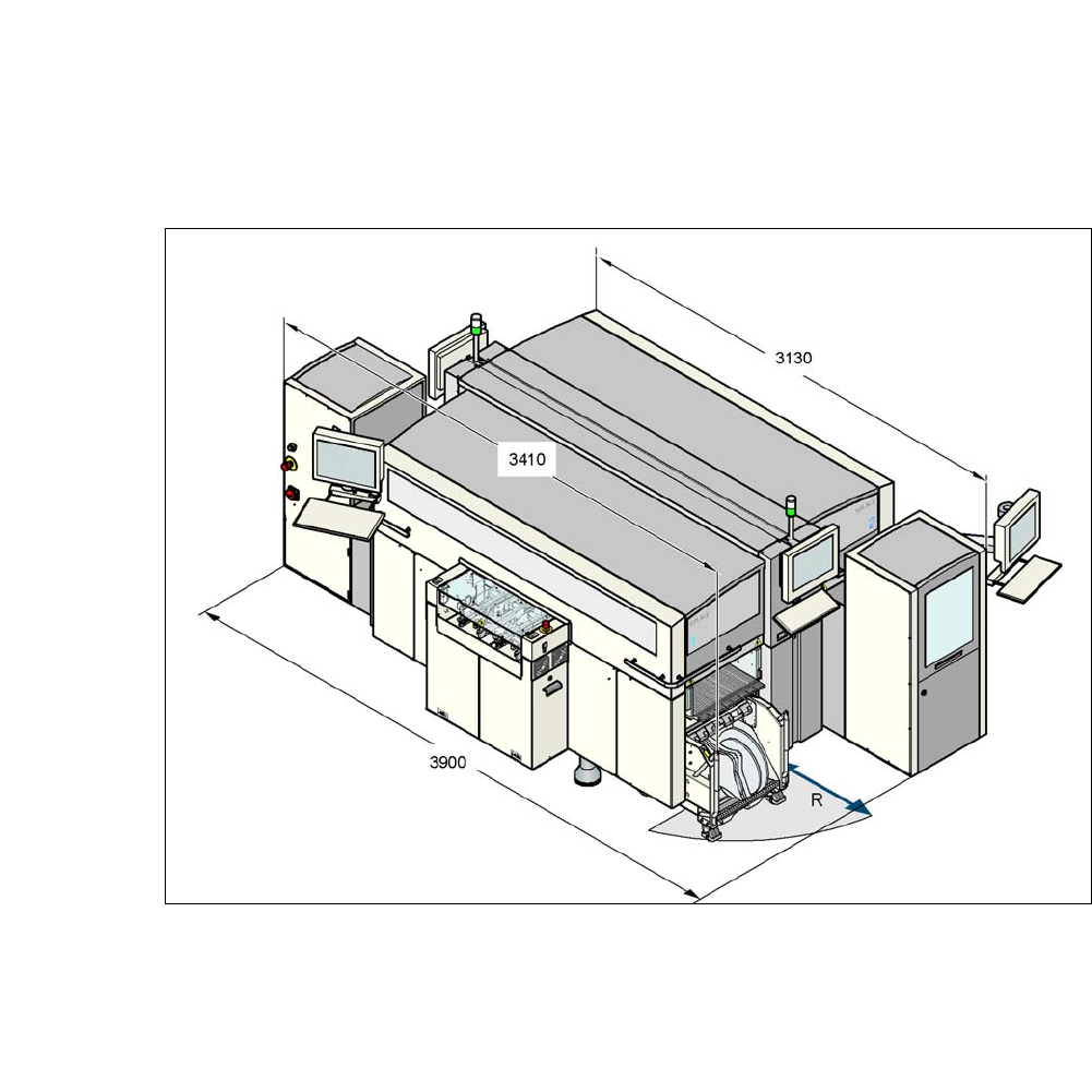
3.4.6 Maneuvering Distance of Component Trolley at CA4 Machines
3
3
Fig. 3.4 - 8 Maneuvering distance of component trolley at CA4 machines with SWS
The maneuvering distance R of component trolleys at CA4 machines is as follows:
– 750 mm with the handles folded down
– 1050 mm with the handles folded up
3 Technical Data User Manual SIPLACE CA-Series
3.4 Dimensions and Weight of the SIPLACE CA From software version SC.708.0 Edition 12/2014 EN -DRAFT
138
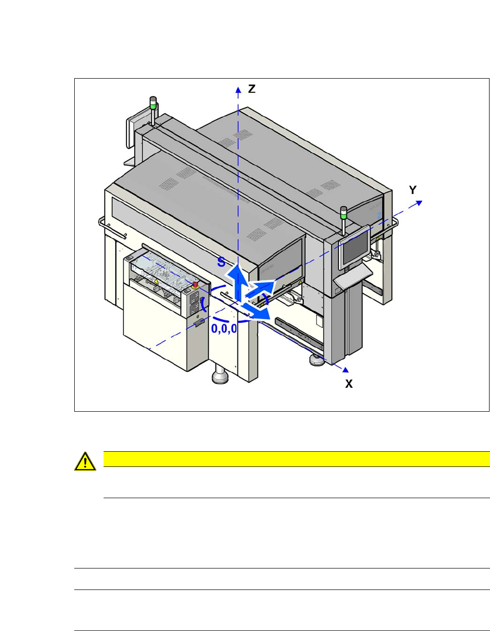
3.4.7 Center of Gravity for CA-Series Machines
3
Fig. 3.4 - 9 Center of gravity for CA-Series machines
3
Center of gravity coordinates:
These center of gravity coordinates relate to placement machines with a PCB conveyor height of
930 mm.
3
CAUTION
Before transportation, remove all changeover tables and SWS from the CA machine.
CA4 machine
Without SWS, without compo-
nent trolley
X coordinate
Y coordinate
Z coordinate
0 mm
0 mm
120 mm height
User Manual SIPLACE CA-Series 3 Technical Data
From software version SC.708.0 Edition 12/2014 EN -DRAFT 3.4 Dimensions and Weight of the SIPLACE CA
139
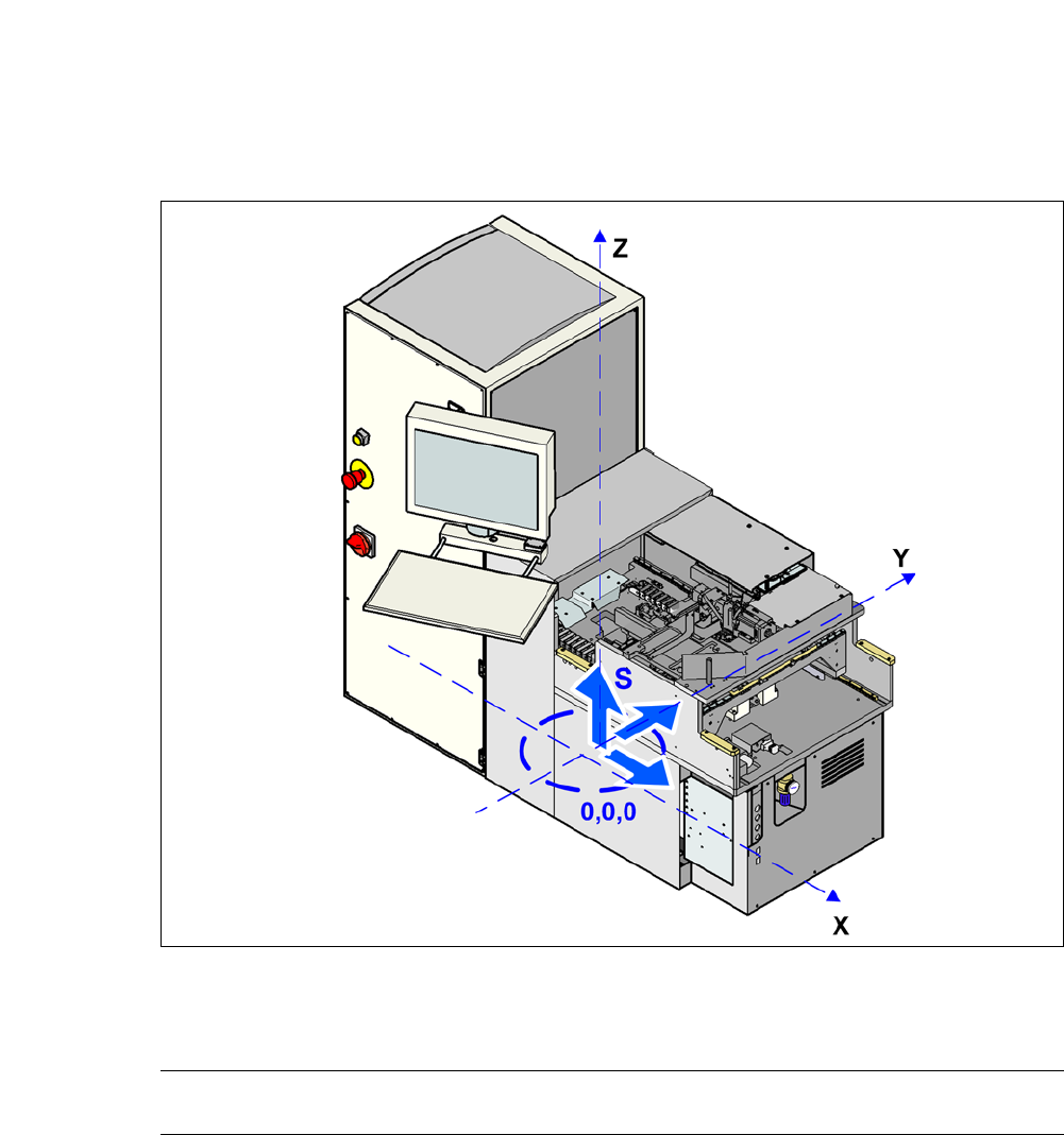
3.4.8 Center of Gravity for SWS
3
Fig. 3.4 - 10 Coordinate system for SWS center of gravity
3
Center of gravity coordinates:
SWS X coordinate
Y coordinate
0 mm
650 mm