00197498-03_UM_SiplaceCA-Serie_EN.pdf - 第255页
User Manual SIPLACE CA-Series 4 SIPLACE Wafer System (SWS) From software version SC.708.0 Edition 12/20 14 4.5 SIPLACE SWS Wafer Stretcher 255 Fitting the downholder plates 4 Fig. 4.5 - 17 W afer support - removing the d…
4 SIPLACE Wafer System (SWS) User Manual SIPLACE CA-Series
4.5 SIPLACE SWS Wafer Stretcher From software version SC.708.0 Edition 12/2014
254
Fitting the stroke ring 4
4
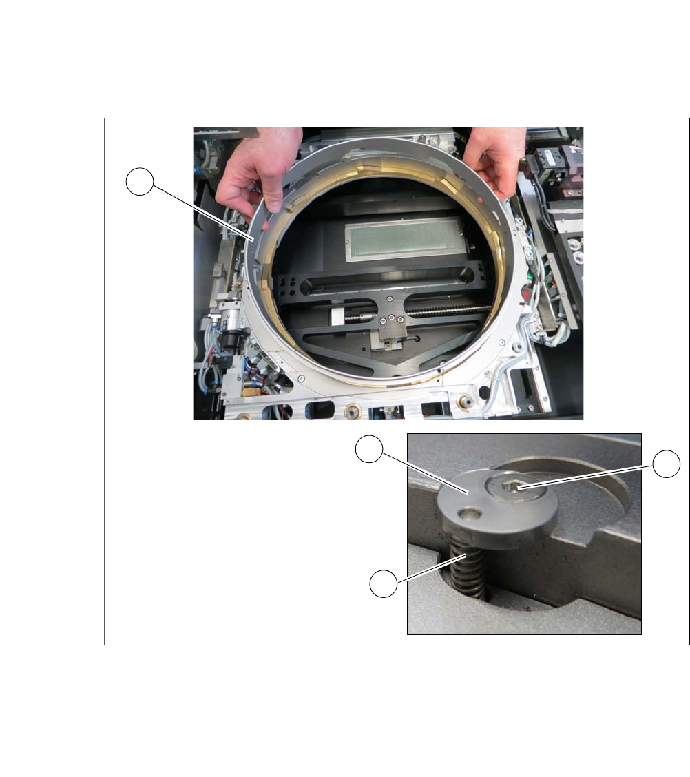
Fig. 4.5 - 16 Wafer support - fitting the stroke ring
Insert the stroke ring (1).
Insert the four springs (3) into the four holes.
Fit the four fixing discs (2) into place.
Fasten the fixing discs into place with the fastening screws (4).
2
3
3
1
User Manual SIPLACE CA-Series 4 SIPLACE Wafer System (SWS)
From software version SC.708.0 Edition 12/2014 4.5 SIPLACE SWS Wafer Stretcher
255
Fitting the downholder plates 4
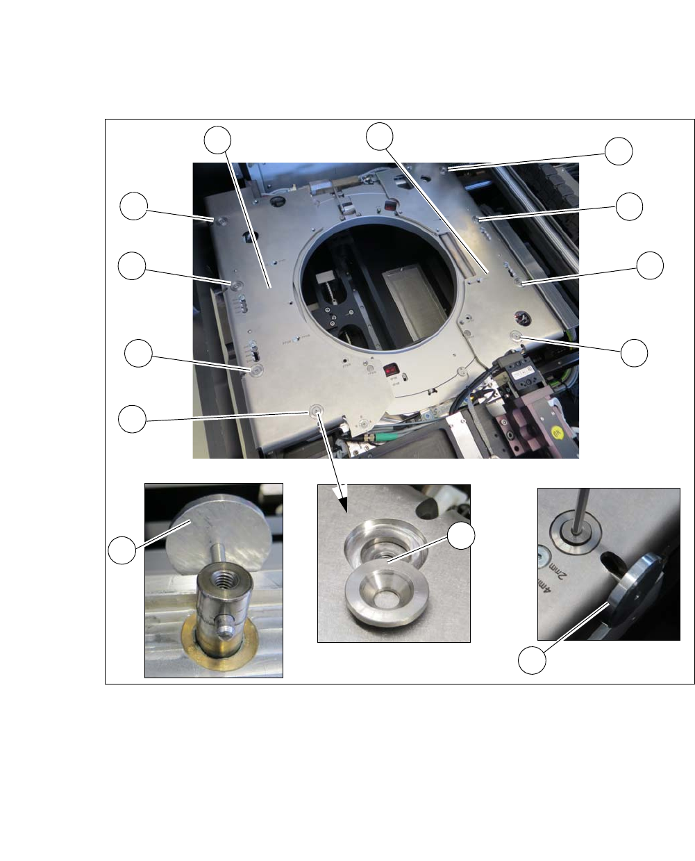
Fig. 4.5 - 17 Wafer support - removing the downholder plate
Align the lifting piston with the auxiliary tool (2) so that the opening points outwards.
Place the downholder plates from the 12" retrofit kit onto the wafer support.
Insert the conical fixing discs (3) into the hole.
Loosely tighten the downholder plates with the screws.
Insert the auxiliary tool (4) into the opening and fix into place with the lifting piston inside.
Tighten all 4 screws (1) on the two downholder plates (5).
1
1
1
1
1
1
1
1
2
3
4
4
4

4 SIPLACE Wafer System (SWS) User Manual SIPLACE CA-Series
4.5 SIPLACE SWS Wafer Stretcher From software version SC.708.0 Edition 12/2014
256
4.5.7.4 Differences in conversion from 12" to 8
The sensors need to be dismantled from the wafer support and fitted onto the 8" expansion plates.
See See "Wafer support - 8" stroke ring removed" on page 249.
The block needs to be dismantled form the clamp and used in place of the clamping level. See
See "Wafer support - loosening the clamp" on page 247.