00197498-03_UM_SiplaceCA-Serie_EN.pdf - 第436页
7 Component and Die Handling User Manual SIPLACE CA-Series 7.4 Used Tape Chute - Component Trolley Docking Unit for SIPLACE X-Serie s From software version SC.708.0 Edition 12/2014 EN - DRAFT 436 7.4 Used T ape Chute - C…
User Manual SIPLACE CA-Series 7 Component and Die Handling
From software version SC.708.0 Edition 12/2014 EN -DRAFT 7.3 SIPLACE X-Series Used Tape Chute
435
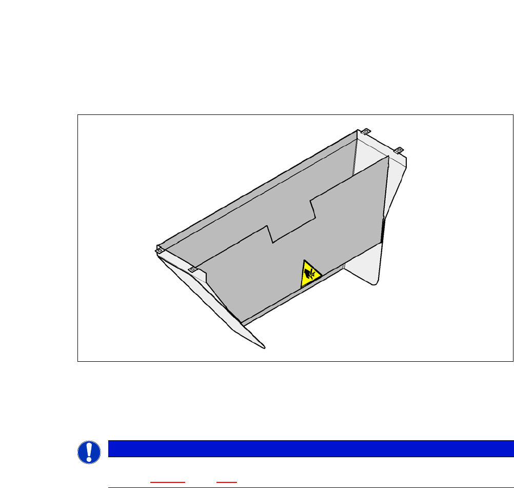
7.3 SIPLACE X-Series Used Tape Chute
7
Fig. 7.3 - 1 Used tape chute for the COT insert of the SIPLACE X-Series
In accordance with the PCB conveyor height, the length of the used tape chute can be set so that
the tape cuttings are directly diverted into the waste tape container of the component trolley.
7
PLEASE NOTE
The used tape chute for the X-Series can only be installed on the COT insert for X-Series
(see fig. 6.14 - 3
, page 389) .
7 Component and Die Handling User Manual SIPLACE CA-Series
7.4 Used Tape Chute - Component Trolley Docking Unit for SIPLACE X-Series From software version SC.708.0 Edition 12/2014 EN -
DRAFT
436
7.4 Used Tape Chute - Component Trolley Docking
Unit for SIPLACE X-Series
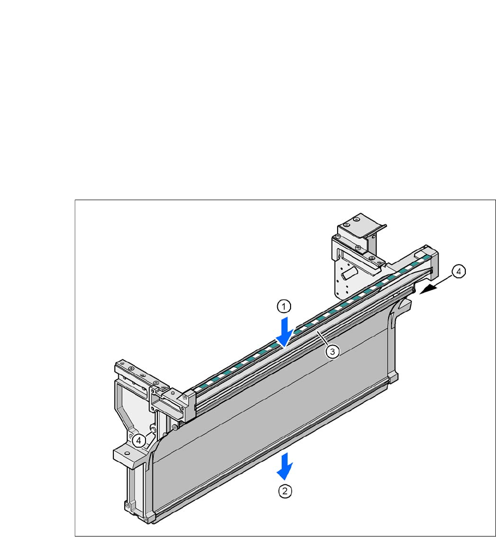
7.4.1 Separating Plate for Tape Pocket Heights up to 12 mm
In the standard version, the used tape channel can guide component tapes with a maximum
pocket height of 12 mm to the pneumatic tape cutter.
7
Fig. 7.4 - 1 Used tape chute for SIPLACE X-Series
(1) Inlet slot for used tape
(2) Outlet slot for the used tape above the pneumatic tape cutter
(3) Dividing plate for tapes < 12 mm (can be removed for tapes > 12 mm)
(4) DIN 93384 screw - M4x20, 2x
User Manual SIPLACE CA-Series 7 Component and Die Handling
From software version SC.708.0 Edition 12/2014 EN -DRAFT 7.4 Used Tape Chute - Component Trolley Docking Unit for SIPLACE X-
Series
437
7.4.2 Dismantling the Partition Plate for Tape Pocket Heights > 12 mm
If you use X feeder modules which process tape with a pocket height of > 12 mm, you will need
to remove the partition plate (item 3 in fig. 7.4 - 1
).
7
Loosen the two hexagon screws (item 4 in fig. 7.4 - 1)
Pull out the separating plate.
7
7
WARNING
Removing the separating plate!
Switch the machine off at the main switch to remove the dividing plate.
Disconnect the machine from the power and compressed air supply.
Lock the machine to prevent unauthorized reactivation, as described in section 2.12,
page 114
.
Wait until the operating pressure for the tape cutter has dropped to 0 MPa.
Do not reach inside the empty tape duct.
PLEASE NOTE
Risk of blockages!
When using feeder modules with low pockets next to feeder modules with high pockets,
there is a risk of blockages in the empty tapes.
Do not position feeder modules with shallow pockets immediately beside feeder mod-
ules with deep pockets.