00197498-03_UM_SiplaceCA-Serie_EN.pdf - 第259页
User Manual SIPLACE CA-Series 5 Setting up and Commissioning From software version SC.708.0 Edition 12/20 14 EN -DRAFT 5.2 Delivery Configuration and Transportation of Placement Machine 259 5 Fig. 5.2 - 2 Delivery config…

5 Setting up and Commissioning User Manual SIPLACE CA-Series
5.2 Delivery Configuration and Transportation of Placement Machine From software version SC.708.0 Edition 12/2014 EN -DRAFT
258
5.2.1.2 Weight of Machine When Ready For Dispatch
The following table contains the weights of the machines prepared for dispatch, including packag-
ing.
5
5.2.2 Configuration When Delivered
The placement machine is delivered with the following configuration:
– The extension kit on the PCB output side (item 1 in fig. 5.2 - 2
) has been removed from the
base machine and dismantled.
– The axis unit (item 2 in fig. 5.2 - 2
) in the extension kit on the PCB output side has been placed
down on a transportation cushion. All cables are attached to the axis unit.
– The track on the single conveyor is set to a width of 210 mm. On the dual conveyor, the width
of conveyor track 1 is 100 mm and of conveyor track 2 is 210 mm. This width setting is sig-
nificant for fine adjustment of the placement machine.
On the dual conveyor, the electrical plug-in connectors for the conveyor motor and light bar-
rier on the left-hand conveyor track are easily accessible and there is still enough space to fit
the output conveyor.
– The output conveyors (item 4 in fig. 5.2 - 2
) from the single and dual conveyor models have
been dismantled. The electrical cables to the conveyor motors and light barriers are discon-
nected.
– Both keyboards (item 6 in fig. 5.2 - 2
) have been disconnected.
– The supporting plates for the keyboards (item 5 in fig. 5.2 - 2
) have been unhooked.
– Both monitors (item 7 in fig. 5.2 - 2
) have been dismantled.
– Both main malfunction displays (item 8 in fig. 5.2 - 2
) have been dismantled.
– All the gantry axes are fixed with shipping braces.
Placement
machine
Dispatch within Europe Dispatch overseas
CA4 4,004 kg 4,504 kg
User Manual SIPLACE CA-Series 5 Setting up and Commissioning
From software version SC.708.0 Edition 12/2014 EN -DRAFT 5.2 Delivery Configuration and Transportation of Placement Machine
259
5
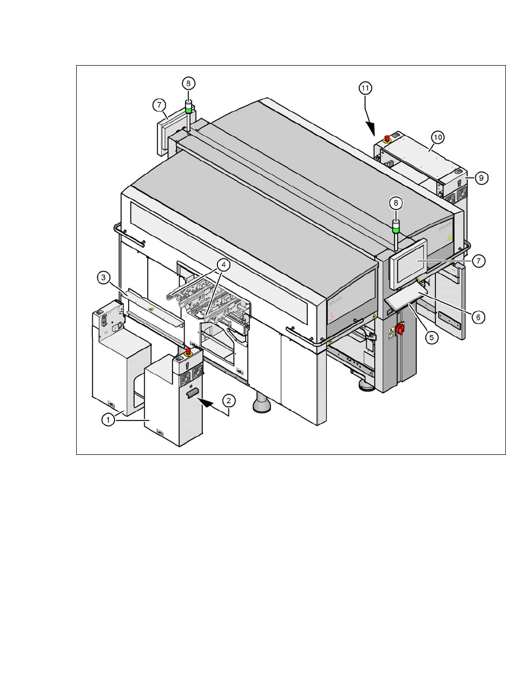
Fig. 5.2 - 2 Delivery configuration of placement machine
(1) Extension kit on the PCB output side - removed and dismantled for delivery
(2) Axis unit on the PCB output side - CA4: Gantries 2 and 3
(3) Transportation cover
(4) Output conveyor
(5) Keyboard supporting plate
(6) Keyboard
(7) Monitor
(8) Main fault indicator
(9) Computer unit on the PCB input side
(10) Extension kit at the PCB input side - can be disassembled if necessary
(11) Axis unit on the PCB output side - CA4: Gantries 1 and 4
5 Setting up and Commissioning User Manual SIPLACE CA-Series
5.2 Delivery Configuration and Transportation of Placement Machine From software version SC.708.0 Edition 12/2014 EN -DRAFT
260
5.2.3 Transporting the Placement Machine in a Crate
5.2.3.1 Services
One of the services provided by ASM Assembly Systems GmbH & Co.KG is the complete inte-
gration of CA-Series placement machines into your production line. With our extensive expertise
and by using the right tools and equipment, we can ensure that the installation process runs
smoothly and efficiently. However, this will require you to clarify the infrastructure aspects in ad-
vance and make any necessary changes at your production facility.
Please note that the safest way to transport the placement machine is always in the transport crate
- or at the very least on the pallet. This will prevent serious damage to the placement machine
caused by the feet colliding with obstacles, for example.
5.2.3.2 Safety instructions
5
5
5
5.2.3.3 Means of Transport
To transport the placement machine on the wooden pallet or in the transport crate, use a fork-lift
truck with the following specifications:
Fork length: Min. 1,800 mm
Carrying power: Min. 6,000 kg
Clear width between forks: Min. 350 mm 5
WARNING
Observe the applicable accident prevention regulations!
The applicable accident prevention regulations concerning the transportation of
heavy goods must be followed.
WARNING
Risk of tilting!
This risk occurs if the required specifications for the fork-lift truck are not observed (sec-
tion 5.2.3.3
)!
Only use the specified fork-lift for transportation.
WARNING
DANGER OF CRUSHING!
Risk of crushing feet when transporting the machine.
Wear special protective shoes.