00197498-03_UM_SiplaceCA-Serie_EN.pdf - 第143页
User Manual SIPLACE CA-Series 3 Technical Data From software version SC.708.0 Edition 12/20 14 EN -DRAFT 3.7 Placement Heads 143 3.7 Placement Heads 3.7.1 SIPLACE SpeedS tar for T op Placement Accuracy (C&P20 M) 3 Fi…
3 Technical Data User Manual SIPLACE CA-Series
3.6 Overviews of the Modules From software version SC.708.0 Edition 12/2014 EN -DRAFT
142
3.6 Overviews of the Modules
3.6.1 Overview of the SIPLACE CA4 Modules
3
3
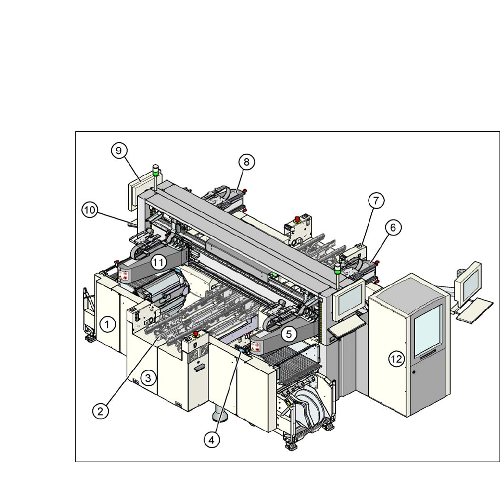
Fig. 3.6 - 1 CA4 machine with SWS - overview of modules
(1) Machine frame (2) PCB conveyor
(flexible dual conveyor)
(3) Extension kit on the PCB input side (4) Component trolley docking unit,
tape cutter, used tape channel
(5) Gantry 1 with placement head (6) Gantry 2 with placement head
(7) Extension kit on the PCB output side (8) Gantry 3 with placement head
(9) Monitor screen (2x) (10) Keyboard (2x)
(11) Gantry 4 with placement head (12) SIPLACE Wafer-System (SWS) at location
2
User Manual SIPLACE CA-Series 3 Technical Data
From software version SC.708.0 Edition 12/2014 EN -DRAFT 3.7 Placement Heads
143
3.7 Placement Heads
3.7.1 SIPLACE SpeedStar for Top Placement Accuracy (C&P20 M)
3
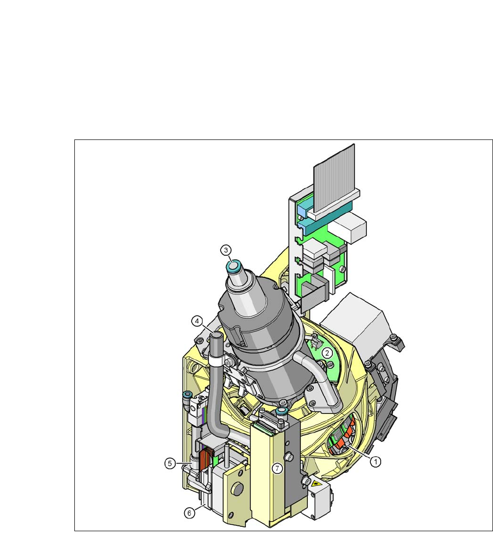
Fig. 3.7 - 1 SIPLACE SpeedStar (C&P20 M) - function groups part 1
(1) DP drive, 20 drives
(2) "Vacuum sensor hold circuit" board
(3) Compressed air connection for 20 Venturi nozzles in the pickup/placement and holding circuit
(4) Line for the exhaust air from the pressure control valve (7)
(5) Return cylinder
(6) Z motor (linear motor)
(7) Pressure control valve
3 Technical Data User Manual SIPLACE CA-Series
3.7 Placement Heads From software version SC.708.0 Edition 12/2014 EN -DRAFT
144
3
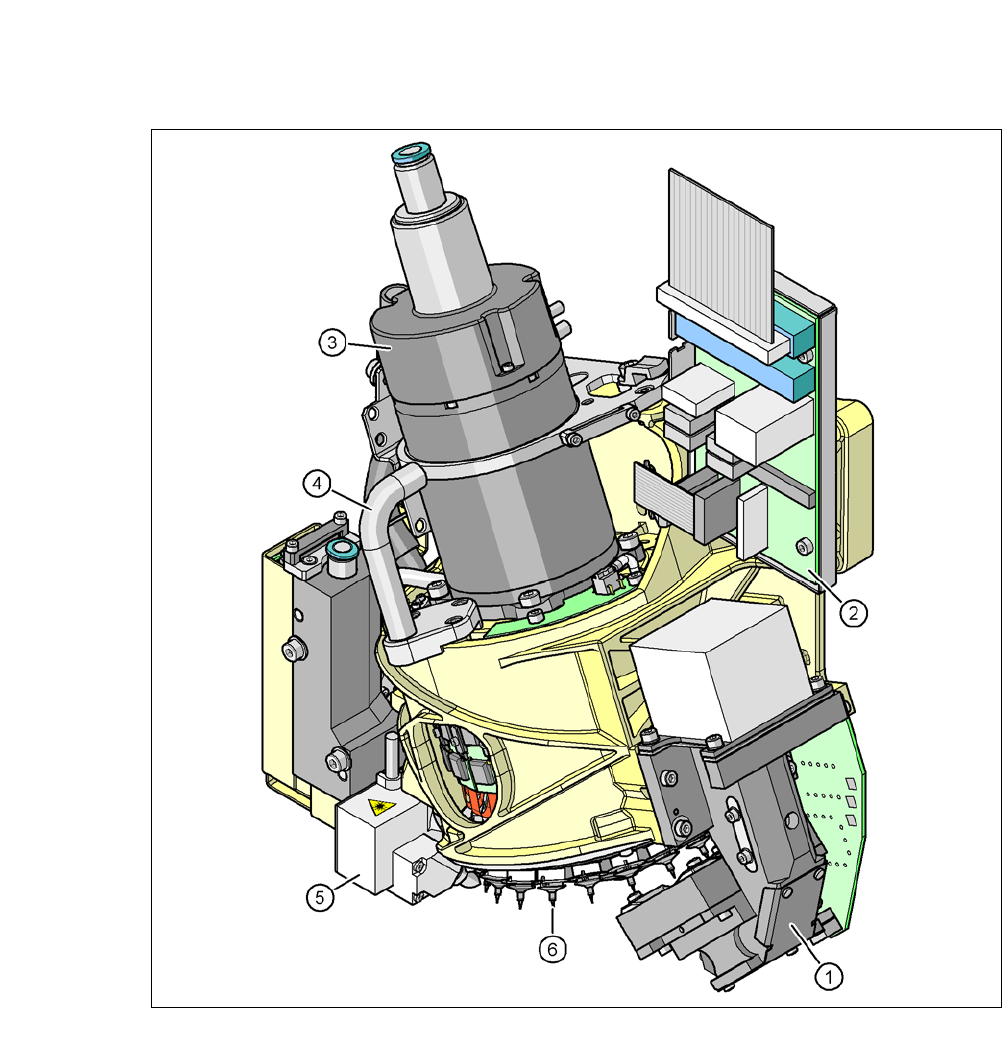
Fig. 3.7 - 2 SIPLACE SpeedStar (C&P20 M) - function groups part 2
(1) C&P component camera, type 23, 6 x 6, digital
(2) Intermediate distributor board
(3) Star motor
(4) Handle
(5) Component sensor
(6) Star with 20 nozzles