00197498-03_UM_SiplaceCA-Serie_EN.pdf - 第274页
5 Setting up and Commissioning User Manual SIPLACE CA-Series 5.4 Infrastructure at the Installation Location From software version SC.708.0 Edition 12/2014 EN -DRAFT 274 5.4.4.1 Danger Notes 5 5.4.4.2 Checking the Mains …
User Manual SIPLACE CA-Series 5 Setting up and Commissioning
From software version SC.708.0 Edition 12/2014 EN -DRAFT 5.4 Infrastructure at the Installation Location
273
5.4.3 Compressed Air Supply to SWS
The compressed air fed to the SWS is directly supplied via the placement machine. (See also
3.3.2
on page 127.)
5.4.4 Mains Supply to Placement Machine
5
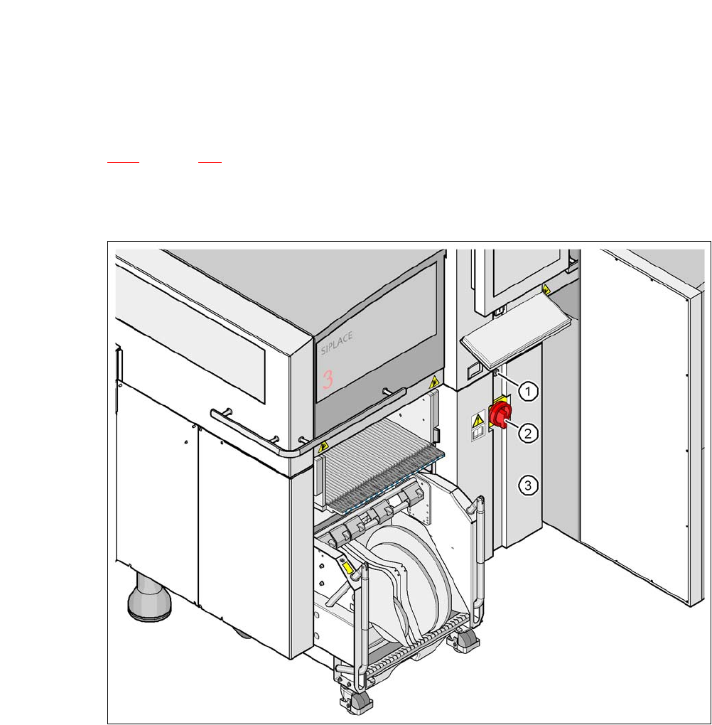
Fig. 5.4 - 2 Position of the power supply on the placement machine
5
(1) Lock
(2) Main power switch secured to prevent switching on again
(3) Cover
5 Setting up and Commissioning User Manual SIPLACE CA-Series
5.4 Infrastructure at the Installation Location From software version SC.708.0 Edition 12/2014 EN -DRAFT
274
5.4.4.1 Danger Notes
5
5.4.4.2 Checking the Mains Power Supply
Check whether the compressed air supply complies with the prescribed machine specifications
(see table in section 3.3
, page 126).
5
5
5.4.4.3 Power Supply Cable - Specification
The following specifications apply to the power supply cable:
5 x 6 mm² for 3 x 380 VAC / 3 x 400 VAC / 3 x 415 VAC
5 x 6 mm² for 3 x 208 VAC / 3 x 230 VAC
The color coding for the wires will depend on the country in which the system is operated.
DANGER
Dangerous voltage levels!
The placement machine is supplied with mains voltage of 3 x 208 V~, 3 x 230 V~,
3 x 380 V~, 3 x 400 V~ or 3 x 415 V~ ± 5 %, 50/60 Hz. This means that some parts of the
system carry potentially lethal voltages - even when switched off at the main power
switch.
Incorrect handling of this machine can therefore result in death or severe injury or consid-
erable damage to equipment.
Always follow the applicable accident prevention and DIN regulations (particularly EN
60204, part 1 or IEC 60204, part 1) and the applicable regulations in your own coun-
try.
Only qualified or appropriately trained personnel may open the covers on the power
supply unit and connect the machine to the power supply.
PLEASE NOTE
Required specifications
To fulfill the required specifications, certain measures are described in the "Network Con-
figuration (Electrics and Compressed Air) for SMD Systems at Customer Site" documen-
tation [00191409-xx].
PLEASE NOTE
Load peaks in power supply
For technical reasons, load peaks occur in the power supply.
Please contact your power company to clarify the mains impedance, if necessary.
User Manual SIPLACE CA-Series 5 Setting up and Commissioning
From software version SC.708.0 Edition 12/2014 EN -DRAFT 5.4 Infrastructure at the Installation Location
275
5
5
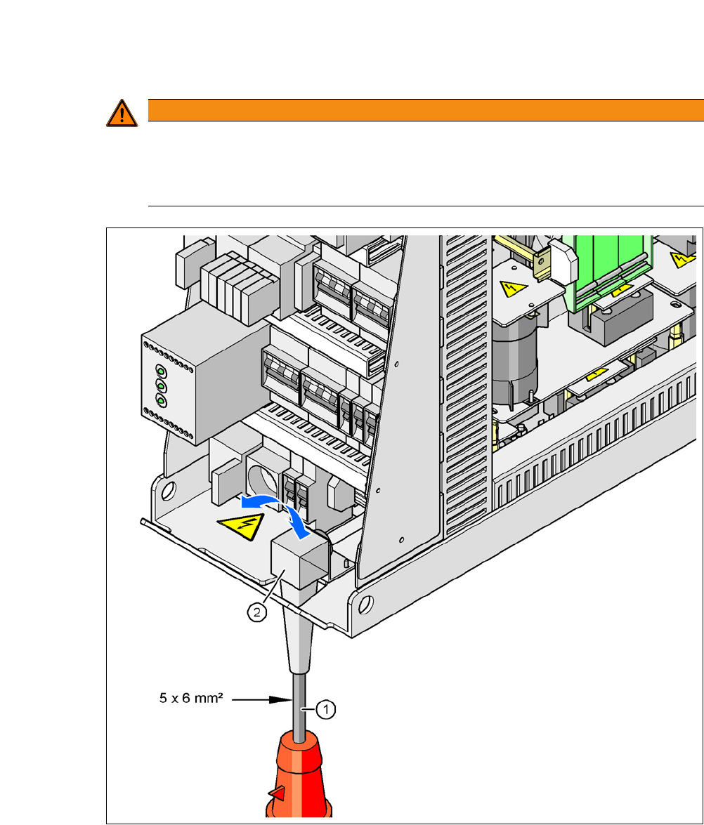
Fig. 5.4 - 3 Cross-section of the main power cable
(1) Power supply cable
(2) Angled cable gland
WARNING
Clear marking of electrical leads!
The electrical leads to each individual machine and to the installed options (e.g. (SWS,
Productivity Lift) must be clearly marked and easy to assign without confusion.
The regulations of the country in which the machine is operated apply.