00197498-03_UM_SiplaceCA-Serie_EN.pdf - 第336页
5 Setting up and Commissioning User Manual SIPLACE CA-Series 5.6 Fitting the SWS From software version SC.708.0 Edition 12/2014 EN -DRAFT 336 5 Fig. 5.6 - 4 Diagram with positions of screws for the SWS at the SIPLACE loc…
User Manual SIPLACE CA-Series 5 Setting up and Commissioning
From software version SC.708.0 Edition 12/2014 EN -DRAFT 5.6 Fitting the SWS
335
5.6.3.4 Final Adjustment of SWS
Use the fork-lift truck or hand lift to push the SWS carefully into the placement machine, as
far as the stop on the bumper.
Carefully lower the SWS with the fork-lift truck or hand lift, until it lies evenly on the contact
bars of the placement machine.
5
The following screws are needed to install the SWS :
–3x M8
–2x M6
– 4 M6 for the angle bracket (2 at the location, 2 at the wafer table)
– 1x fitting screw
5
Fasten the back clamping claw (6) loosely with an M8 screw.
Insert the remaining screws and tighten loosely.
5
Fasten the M6 screws (item 4 and 5) in succession, with a torque of 10 Nm.
Fasten the M8 screws (item 1, 2 and 6) in succession, with a torque of 18 Nm.
Tighten the fitting screw in item 3 with a torque of 13-14 Nm.
Tighten the angle bracket for fixing the wafer table with the M6 screws (items 7 and 8).
Fix the angle bracket with the 2 M6 screws to the wafer table.
CAUTION
Risk of tilting!
When lowering the hand lift before the screws of the SWS have been tightened, there is
a risk that the SWS could tilt.
Do not lower the hand lift too far before the SWS screws have been tightened.
Enlist the help of a second person to check the stability of the SWS during lowering.
PLEASE NOTE
Order of screws
During final installation, observe the following order of screws.
PLEASE NOTE
The correct position of the SWS is ensured with the help of the fitting screw and the con-
tact rods in the placement machine.
5 Setting up and Commissioning User Manual SIPLACE CA-Series
5.6 Fitting the SWS From software version SC.708.0 Edition 12/2014 EN -DRAFT
336
5
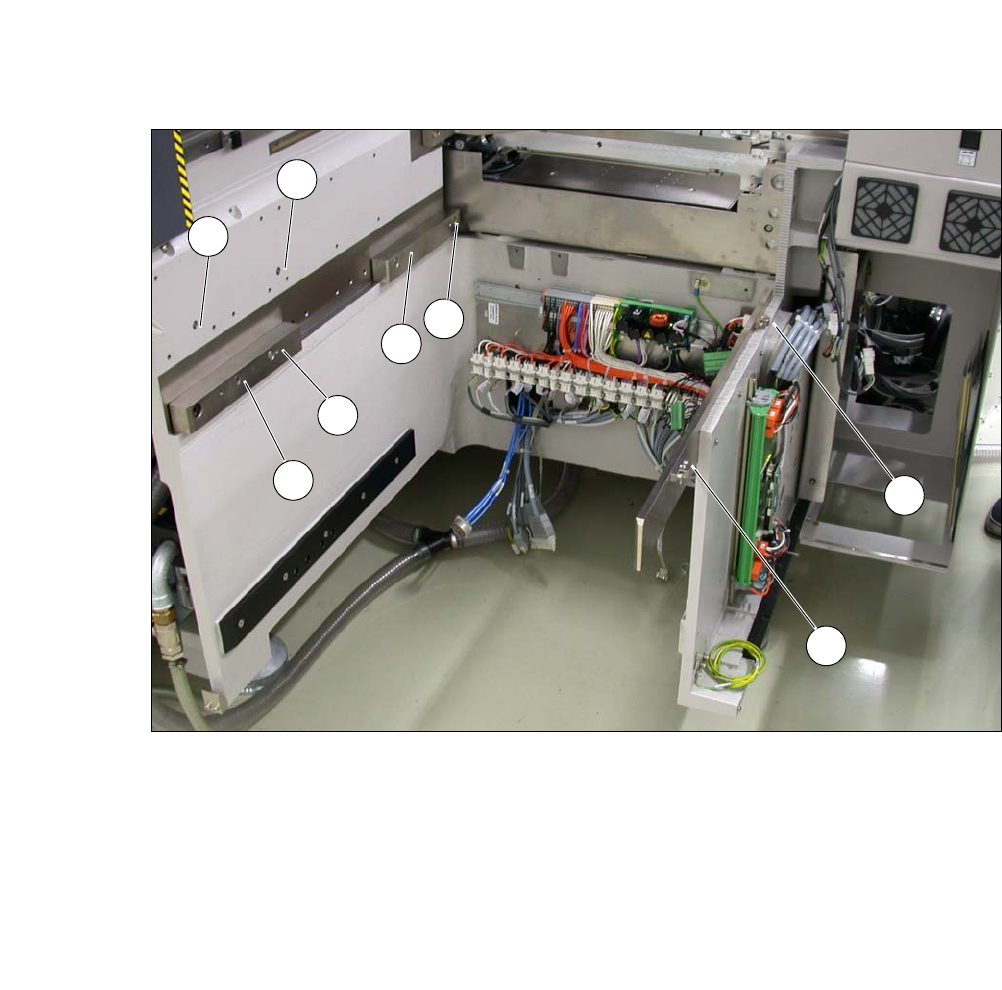
Fig. 5.6 - 4 Diagram with positions of screws for the SWS at the SIPLACE location
You can now remove the fork lift/hand lift.
(1) M8 (2) M8
(3)Fitting screw (4)M6
(5) M6 (6) M8 for clamping claw
(7) M6 for angle bracket (8) M6 for angle bracket
2
3
5
4
1
7
8
6
User Manual SIPLACE CA-Series 5 Setting up and Commissioning
From software version SC.708.0 Edition 12/2014 EN -DRAFT 5.6 Fitting the SWS
337
5.6.4 Removing the Transport Locks
– Remove all transport locks:
– Flip rotary axis
– Wafer table (X/Y axis)
– Wafer changer feed axis (if present)
5.6.5 Removing the Corrosion Protection from the Guide Rails
Check whether the SWS has been treated with corrosion protection agent. This must be removed
before setting up the SWS.
5
5
5.6.6 Power supply
After performing final adjustment, connect the SWS to the power supply.
CAUTION
Reduced product life of bearings and guide rails!
If the corrosion protection agent is mixed with the bearing grease on the axes this can
greatly reduce the service life of the bearings and guide rails.
You should therefore remove the corrosion protection from all the axes and bearings
when you traverse the machine axes for the first time during commissioning.
Grease all the axes and bearings with the grease described in the maintenance in-
structions.
CAUTION
Risk of damaging bearing grease!
Alcohol will damage the bearing grease in the guide carriages.
When cleaning the guide rails and scales, make sure that alcohol does not get into
the guide trolley.