00197498-03_UM_SiplaceCA-Serie_EN.pdf - 第474页
8 Station Extensions User manua l SIPLACE CA-Series 8.3 Component Camera for the TwinStar, FC Camera From software version SC.708.0 Edition 12/2014 EN -DRAFT 474 8.3 Component Camera for the T winS t ar , FC Camera 8.3.1…

User manual SIPLACE CA-Series 8 Station Extensions
From software version SC.708.0 Edition 12/2014 EN -DRAFT 8.2 Sensor for the Component Reject Bin
473
8.2 Sensor for the Component Reject Bin
[00116848-xx] Query component reject bin X-Series/D3
The sensor for the component reject bin monitors whether the reject bin is seated correctly on its
mount.
– If the reject bin was not inserted correctly, the machine cannot be started.
– If the reject bin jumps out of its mount during the placement process, the machine is stopped
immediately to avoid a head crash.
Each reject bin can be monitored by a separate sensor.
8
PLEASE NOTE
When using a SIPLACE SpeedStar (C&P20 M) at a location without SWS, we recommend
that you install the optional sensor for the component reject bin.
8 Station Extensions User manual SIPLACE CA-Series
8.3 Component Camera for the TwinStar, FC Camera From software version SC.708.0 Edition 12/2014 EN -DRAFT
474
8.3 Component Camera for the TwinStar, FC Camera
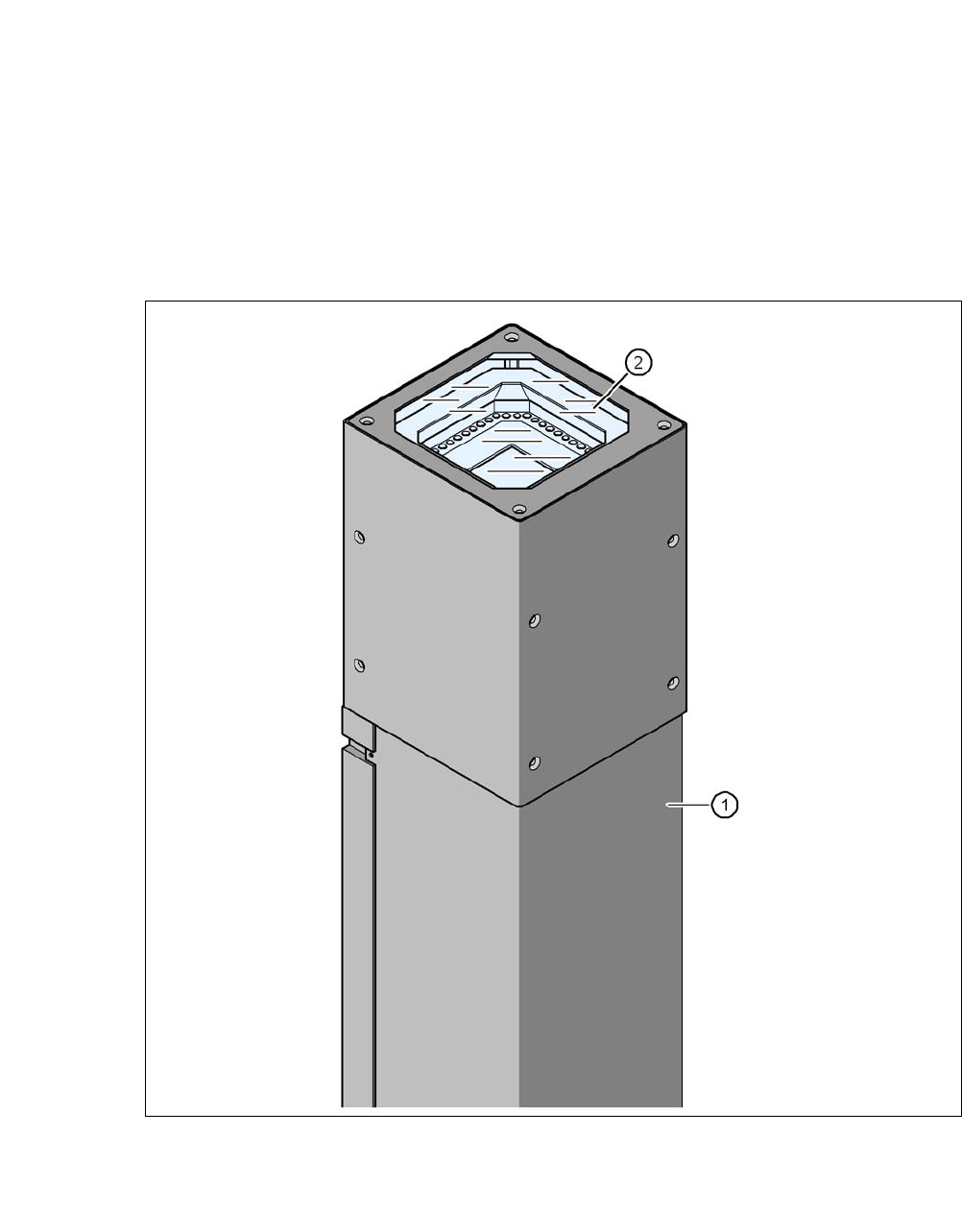
8.3.1 Stationary P&P Component Camera (Type 25) 16 x 16, Digital (FC Camera)
Item no. 00119718-xx Stationary component camera 16x16 digital, type 25
8
Fig. 8.3 - 1 Stationary P&P component camera (type 25) 16 x 16, digital (FC camera)
(1) Camera housing with integral camera and camera amplifier
(2) Glass plate - illumination and lens levels below
User manual SIPLACE CA-Series 8 Station Extensions
From software version SC.708.0 Edition 12/2014 EN -DRAFT 8.3 Component Camera for the TwinStar, FC Camera
475
8.3.2 Safety Instructions
8
8.3.3 Technical Data
8
8
8
WARNING
Placement head change
When changing the placement head from the TwinStar to the SpeedStar, dismantle
the stationary component cameras type 33, 55 x 45, digital and 25, 16 x 16 digital (FC
camera) of the TwinStar, to prevent the SpeedStar from colliding with the camera
housings.
When changing the placement head from TwinStar to MultiStar, the stationary com-
ponent camera, type 33, 55 x 45, digital, is fitted in the bottom position.
Component dimensions 0.2 x 0.2 mm² to 16 x 16 mm² for simple measurement of component
Component range 0402 to SO, PLCC, QFP, sockets, plugs, BGA, special components,
bare dies, flip-chips, shields
Min. lead pitch 0.25 mm
Min. lead width 0.1 mm
Min. ball pitch 0.14 mm
Min. ball diameter 0.08 mm
Field of vision 19.4 x 19.4 mm²
Illumination mode Front-illumination (6 levels, programmable as required)