YRM20_Ope_E.pdf - 第110页
2. Operation screen and buttons 2-13 Chapter 2 Basic operation 7. Capture button Captures the displayed image. The captured data (JPEG format) is stored in the D:\ScreenShot folder (maximum folder size: approx. 10MB), wi…
2. Operation screen and buttons
2-12
Chapter 2 Basic operation
█
Buttons and parameter input boxes
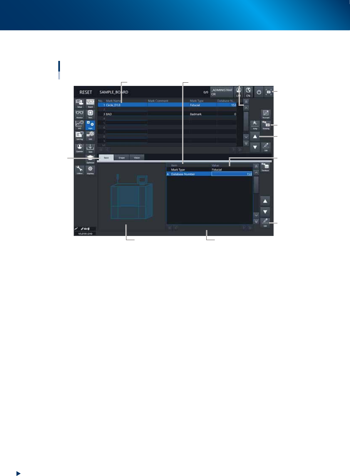
Various types of buttons, selection tabs and parameter input boxes are used on the operation screen.
Operation screen basic elements
Mark screen
1
1
2
3
4
5
6
7
Parameter listData No. list
[Edit] button
24202-KMX-00
1. Scroll bar and button (vertical/horizontal)
Use the scroll bars or arrow buttons to see hidden items in the data No. list or parameter list.
2. Operation button
Press these buttons to open the next operation screen or dialog box.
3. Line up/down button
Use these buttons to move the cursor up or down through the data No. list or parameter list.
4. Parameter input box
Select, enter or edit parameters here. When the keyboard is used, double-click on a parameter input
box to enter or edit the data.
To operate the touch panel for data entry, press the corresponding [Edit] buttons on the right side of the
screen to have the edit box pop up.
5. Selection tab
Select this tab to switch the parameter input screen.
6. Assistant screen
Shows an illustration or information useful for parameter input or editing.
Alphabet characters shown in the parameter list and in the illustration on this screen correspond to each
other.
2. Operation screen and buttons
2-13
Chapter 2 Basic operation
7. Capture button
Captures the displayed image. The captured data (JPEG format) is stored in the D:\ScreenShot folder
(maximum folder size: approx. 10MB), with a file name consisting of the date and time.
When a USB flash memory is inserted into the machine’s USB port and system backup is performed, a
“ScreenShot” folder is created in the root of the USB flash memory to acquire the captured data stored
in the machine. (The captured data stored in the machine is moved to the USB flash memory.)
c
CAUTION
• When saving data in a USB flash memory, make sure to use the USB flash memory designated by YAMAHA.
• If you specify the destination to save the data on the “Screen Shot Setting” window (Press the [Setup] – [Software
Setting] – [Information] – [Screen Shot Setting] buttons), the captured data cannot be saved in the USB flash memory
even by performing System backup.
►
About error screen
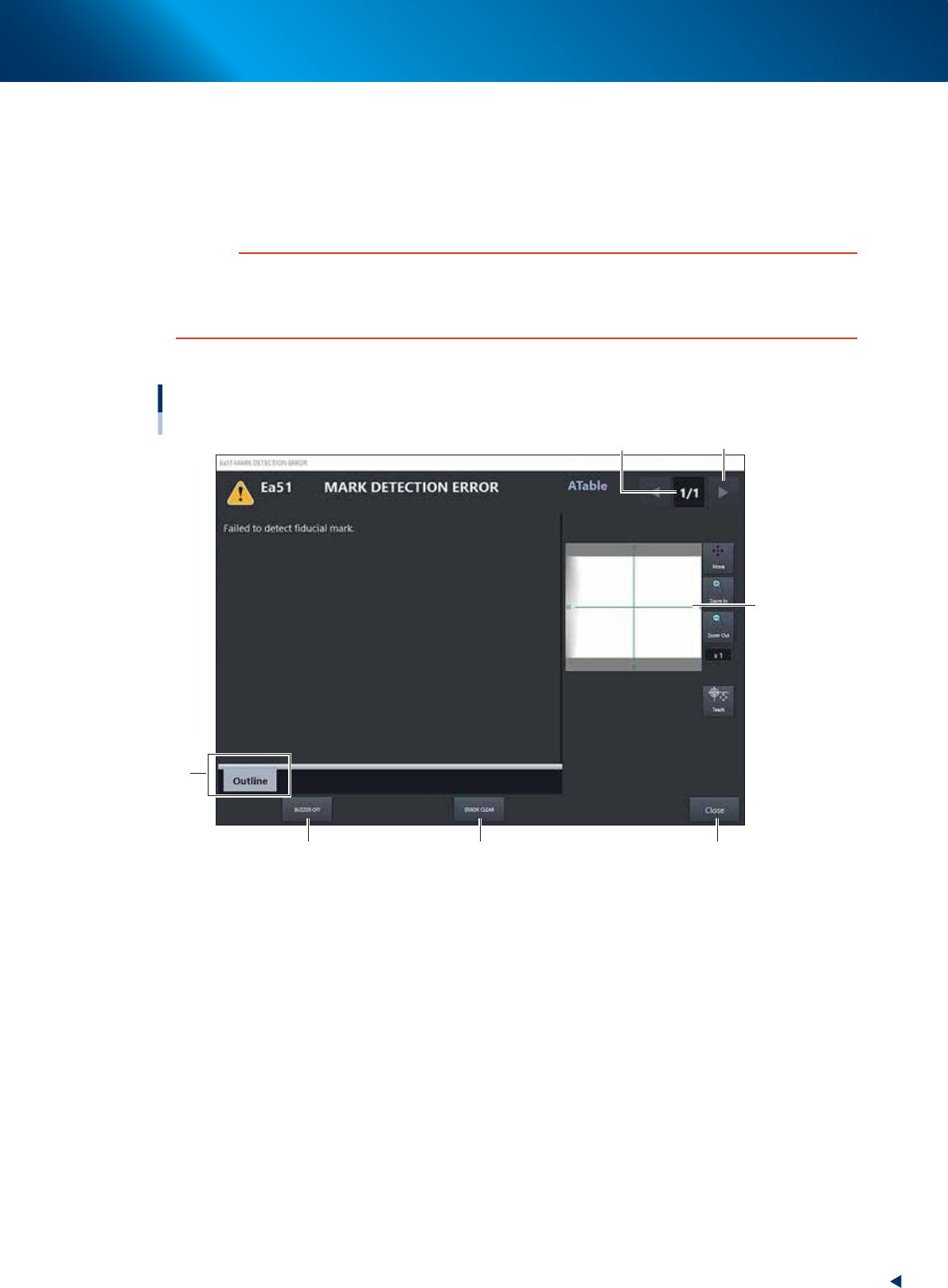
Constitution of error screen
Mark detection error
1
2
3
6
4 5
[Error Switching] button
24203-KMX-00
1. Error count display
Shows the currently displayed error and the total number of errors. If two or more errors occurred,
use the [Error Switching] buttons (right/left arrow buttons) to switch to other error screens.
2. Message switching tab
• Outline
Displays a message for the operator.
• Detail
Displays a message for the administrator/supervisor or service personnel. This tab does not appear
unless a message is available.
3. Recognition image display (component pickup error and mark recognition error screens)
If an error has occurred in image processing during component pickup or mark recognition, the error
image is displayed here.

2. Operation screen and buttons
2-14
Chapter 2 Basic operation
4. [BUZZER OFF]
Turns off the buzzer.
5. [ERROR CLEAR]
Clears the error that has occurred.
6. [Close] button
Closes the error screen without clearing the error.
TIP
The positions where errors occurred can be checked graphically by opening the [Monitor] - [Production] tab after closing
the error screen by pressing the [Close] button. Pressing the [Error Detail] button on the [Production] screen redisplays the
error message. See"3.1 Production" in this chapter for the [Production] screen.