YRM20_Ope_E.pdf - 第134页
3. Displaying the production monitors 2-37 Chapter 2 Basic operation • No. Displays the component No. (Par ts screen data No.). • Set No. Displays the feeder set No. • Par ts Name Displays the component name. • T ape T y…
3. Displaying the production monitors
2-36
Chapter 2 Basic operation
3.8 Pick Pos. (Pickup position offset)
n
NOTE
Pickup position offset function applies to the components satisfying the following conditions.
• The correct Mode on [Machine] - [Specification Information] - [Pick Position Specification] is set to either "Use" or "Use
with Feeder Correction".
• Component picked up with a nozzle that the "Available" on [Machine] - [Specification Information] - [Pick Position
Specification] is set to "Use".
• Component that "E: Pick Pos Correction" is set to "Use" on [Parts] - [Option] tab screen of the board data.
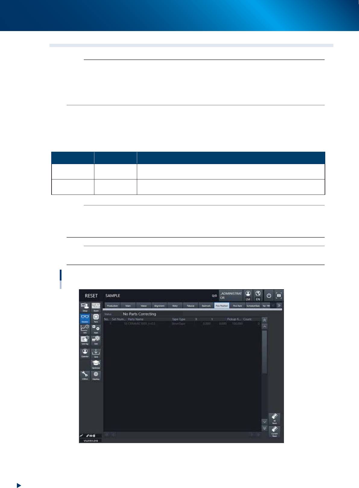
This screen appears when the pickup position offset function is used. This screen allows to check how the
pickup position of the object component (feeder) is corrected. If either the X or the Y correction amount
exceeds the warning zone or the error zone set up in the machine setting, the corresponding component in
the components list changes its color.
►
Display color
Color of row Status Description
Yellow Warning
Exceeds warning level figure for each nozzle data set in pickup position offset
specifications.
Red Error
Exceeds error level figure for each nozzle data set in pickup position offset
specifications.
n
NOTE
Warning generated : The machine generates an error message. The yellow lamp on the signal lamp tower flashes.
The machine, however, can continue the operation.
Experiencing error : The machine generates an error message when finishing producing one board.
The machine cannot continue the operation.
n
NOTE
The numerical values specified in the warning level and error level of the pickup position offset specification are machine
data setting items. Accessing such parameters require the administrator level of authority.
Monitor: Pick Pos. (Pickup position offset)
24219-KMX-00

3. Displaying the production monitors
2-37
Chapter 2 Basic operation
• No.
Displays the component No. (Parts screen data No.).
• Set No.
Displays the feeder set No.
• Parts Name
Displays the component name.
• Tape Type
The Tape Type shows the type of tape when the machine processes component tapes. It shows the
method of supplying components when processing tray components.
• X (mm), Y (mm)
Displays the amount of pickup position offset. The figure shown is the amount of error from the
nozzle center position towards the X-direction and Y-direction.
• Pick Rate (%)
Displays the component pickup rate of the nozzle for which the pickup position offset function is on
(enabled).
• Count
Displays the number of components that were picked and placed by the nozzle for which the pickup
position offset function is on (enabled).
• [All Reset] button
This button clears and resets pickup position offset data for all components shown on the monitor.
• [Current Reset] button
Clears and resets pickup position offset data for a component selected from among the components
shown on the monitor display.
3. Displaying the production monitors
2-38
Chapter 2 Basic operation
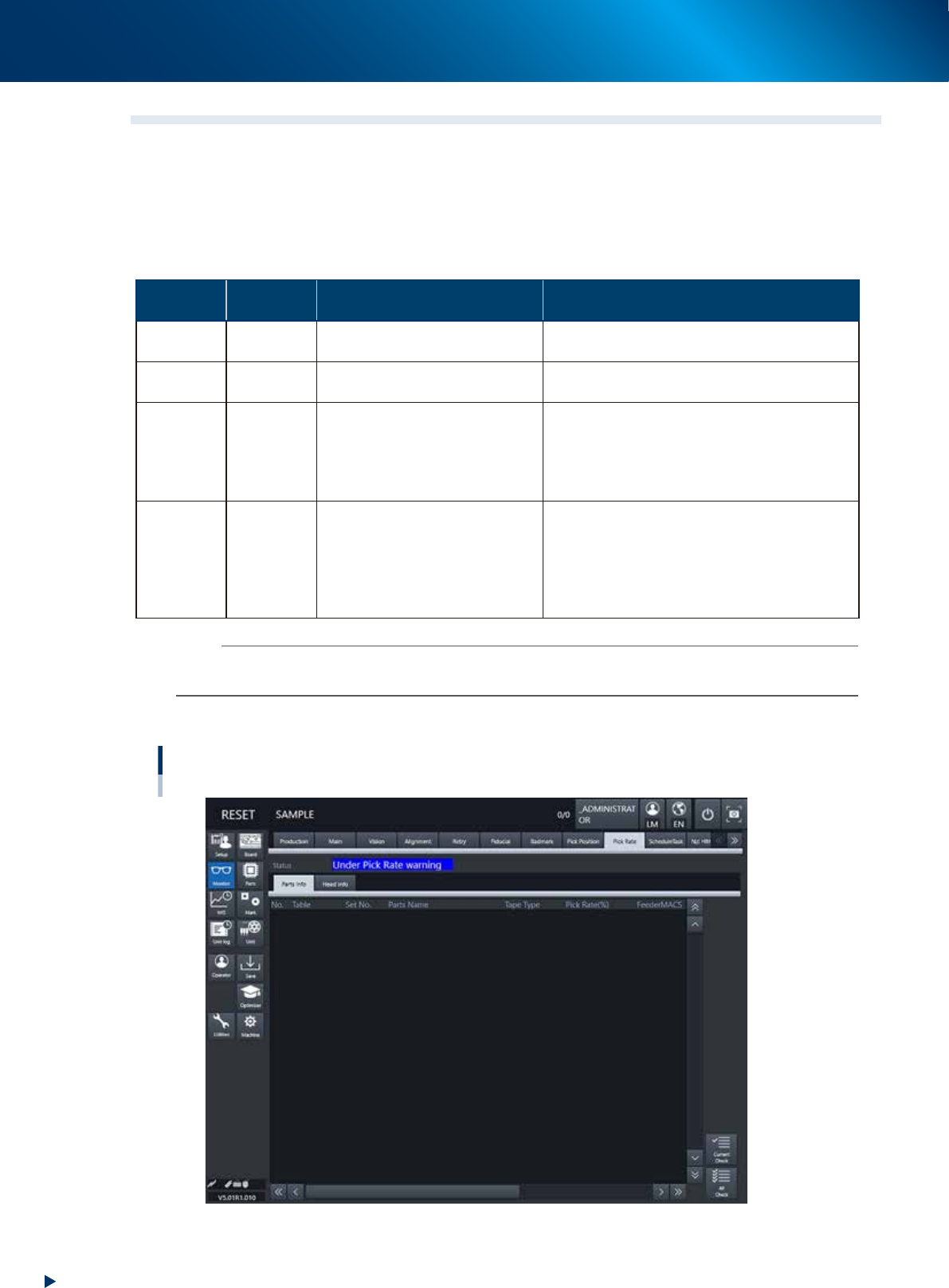
3.9 Pick Rate Warning
This screen appears when using the pickup rate warning function. When clicking the tab to switch the
display, the screen allows checking for a drop in the component pickup rate on each component or head.
The pickup rate is reset in real-time after mounting a group of components. However, if a particular
component or head is not used then its row will not appear on the display. Pickup rates can be monitored
by color during operation.
►
Display color
Color of
row
Status Pickup Rate Description
White 100% to [caution (yellow)]%
Pickup rate is above [caution (yellow)]% and
below (or equal to) 100%.
Yellow Caution
[caution (yellow)]% to [warning
(red)]%
Pickup rate is above [warning (red)]% and below
(or equal to) [Caution (yellow)]%.
Red Warning [warning (red)]% to 0%
Pickup rate is above (or equal to) 0% and below
(or equal to) [warning (red)]%.
If the machine setting of the stop control is set
to “Use”, the machine stops while generating an
alarm. The default setting is “Not Use”.
Pink
Watch-
and-wait
mode
Optional
When the pickup rate is [warning (red)]% or
less, pressing the [Current Check] or [All Check]
button enables "watch-and-wait" mode and the
color of the "red" row(s) changes to "pink".
Note that operation is not stopped in this mode
even if stop control setting is made.
n
NOTE
Numerical values (%) in brackets [ ] are machine data setting items. Accessing such parameters require the administrator
level of authority.
█
[Parts Info] tab
Monitor: Pick Rate Warning
Parts info
24220-KMX-00