YRM20_Ope_E.pdf - 第30页
Chapt er 1 Unit name s and f unction s Contents 1. Machine main unit 1- 1 2. Operation panel and data input unit 1-5 2.1 Operation display s creen/Operation but ton 1 -6 2.2 Keyboar d (option) 1-8 2.3 Other connection po…
1. Using this manual
iii
About this manual
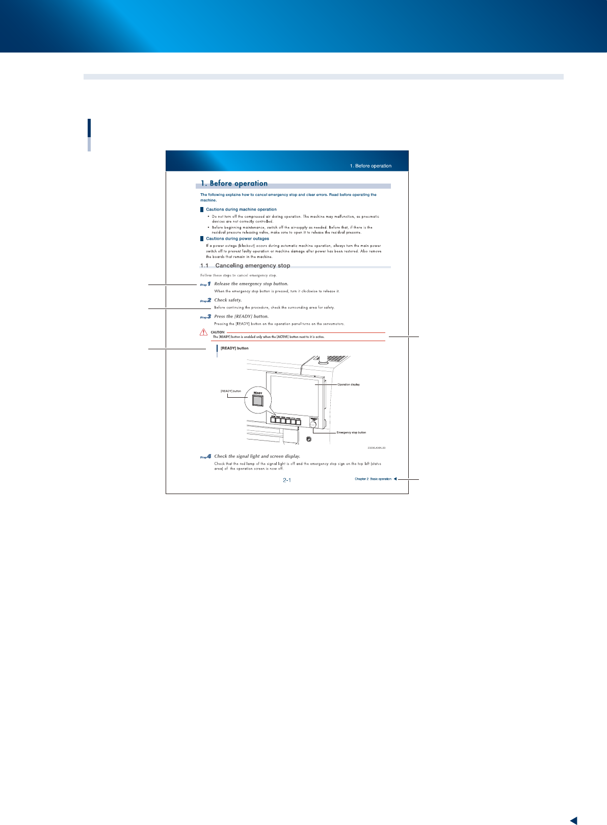
1.2 Page layout
The description below shows a typical page layout used in this manual.
Typical page layout
Step
Substep or
description of step
Figure, picture
or table caption
Note, Caution
or Warning
Chapter title
23000-KMX-00
■
Step
Describes the procedure for each operation.
■
Substep or description of step
Describes steps in detail.
■
Figure or table caption
This is the title of the figure or table and appears at the upper left.
■
Note, Caution or Warning
These are explained in detail in "Safety instructions".

Chapter 1 Unit names and functions
Contents
1. Machine main unit 1-1
2. Operation panel and data input unit 1-5
2.1 Operation display screen/Operation button 1-6
2.2 Keyboard (option) 1-8
2.3 Other connection ports 1-9
3. Head unit 1-10
3.1 Component pick-and-place head 1-11
3.1.1 RM Head unit 1-11
3.1.2 HM Head unit 1-13
3.2 Nozzle types 1-14
3.3 Nozzle station (option) 1-16
3.3.1 Overview of Nozzle station 1-16
3.3.2 Nozzle holder 1 and 2 1-17
3.3.3 Type A nozzle holder 1-18
3.3.4 Type B nozzle holder 1-19
3.3.5 Attaching/Detaching nozzle holder 1-20
3.4 Blow station 1-22
3.4.1 Shaft-blow function 1-22
3.4.2 Manual nozzle shaft blow procedure 1-23
3.4.3 Automatic nozzle shaft blow procedure 1-28
3.4.4 Shaft blow dump of very small components 1-31
3.5 Vacuum pump ( RM head) 1-32
3.5.1 Vacuum pump (RM head) 1-32
4. Component supply section 1-33
4.1 Machine layout 1-33
4.2 Supplying component tape 1-35
4.2.1 Feeder exchange carriage 1-35
4.2.2 Feeder exchange carriage attaching section of machine 1-38
4.2.3 Attaching/Detaching upper cover 1-41
4.3 One-stop cover (option) 1-45

4.4 Non-stop feeder change 1-46
Feeder removing conditions : 1. Setting "Skip Retry" 1-48
Feeder removing conditions : 2. Pressing [Feeder Remove] button 1-49
Feeder removing conditions : 3. Setting alternative component function 1-50
5. Conveyor 1-53
5.1
Conveyor unit 1-53
5.2 Sensor layout of conveyor unit 1-55
5.3 Board position in machine by board size 1-57
6. Recognition unit 1-58
6.1 Fiducial, Scan and Side-view camera 1-58
6.2 Side-view function (Scan camera / Side-view camera) 1-60
6.3 Multi-view cameras 1-61
7. Axis configuration 1-62
7.1 Head unit axis configuration 1-62
7.1.1 RM head unit 1-62
7.1.2 HM head unit 1-63
7.2 Main axis and conveyor axis configuration 1-64