YRM20_Ope_E.pdf - 第54页
3. Head unit 1-23 Chapter 1 Unit names and functions 3.4.2 Manual nozzle shaft blow procedur e T his section explains how to manually perform a nozzle shaft blo w at any desired timing. 1 Open the [Unit] – [Head] screen.…
3. Head unit
1-22
Chapter 1 Unit names and functions
3.4 Blow station
3.4.1 Shaft-blow function
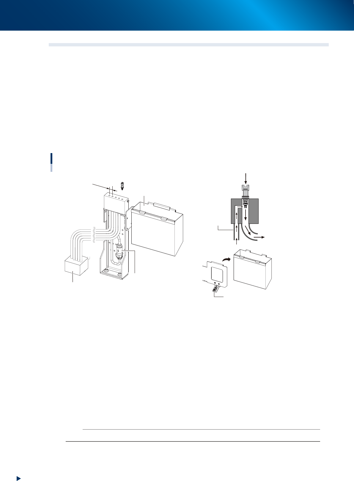
The air-blow station provides a high-pressure air blowing cleaning function to blow foreign matter from the
nozzles, inside the shafts and nozzl tip (This motion is called Nozzle Shaft blow).
The air-blow stations are installed at front and rear side of machine.
Five holes shown in the figure below are used to blow the heads separated in groups. See"3.4.2 Manual
nozzle shaft blow procedure" for practical method.
Here, components are normally disposed into the dump box. But regarding to the disposal of very small
components as such 1005 size or smaller, if some components or dust are recognized at checking after
disposal operation (by negative pressure check or side view recognition), the air-blow station continues shaft
blow dump to dispose very small components.
See the section"3.4.4 Shaft blow dump of very small components" for practical method.
Air-blow station and dump box
Dump box
confirmation sensor
Dump box
Exhaust box
Shaft blow
Side blow
Air-blow station filter
12mm
23118-KMX-00
■
Side blow
Cleans the nozzle tip by air-blow from side when the nozzle shaft-blow is performed.
■
Air-blow station filter
The filter for the side-blow line in the air-blow station.
■
Dump box
A box to dispose the discarded components.
■
Dump box confirmation sensor
Checks the dump box presence and floating status.
■
Exhaust box
Stores dust and vert small chips disposed by the nozzle shaft-blow.
n
NOTE
The automatic operation cannot be started without the dump box in its position.
3. Head unit
1-23
Chapter 1 Unit names and functions
3.4.2 Manual nozzle shaft blow procedure
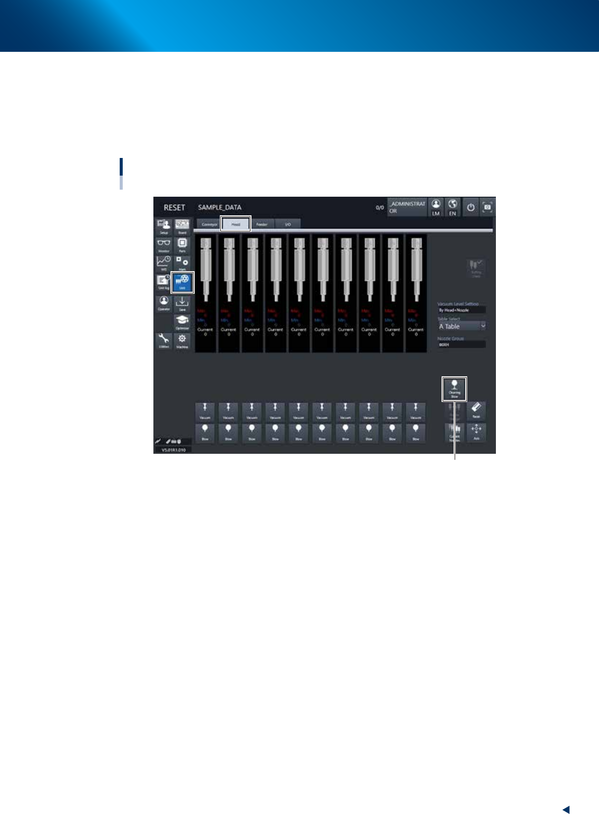
This section explains how to manually perform a nozzle shaft blow at any desired timing.
1
Open the [Unit] – [Head] screen.
2
Press the [Cleaning Blow] button.
Nozzle shaft blow
HM head unit
[Cleaning Blow] button
24100-KMX-00
3. Head unit
1-24
Chapter 1 Unit names and functions
3
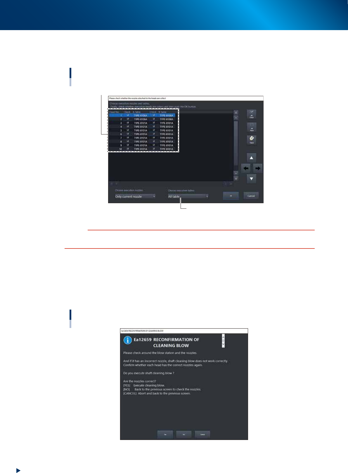
Specify the nozzles you want to clean by nozzle shaft blow.
The "Nozzle Setting" screen will appear. Select the table where the nozzle shaft cleaning blow is
performed, put a check mark on the nozzles, and then press the [OK] button.
Nozzle Setting screen
Select the check boxes for the nozzles you want to clean by nozzle shaft blow.
Select the table.
24101-KMX-00
c
CAUTION
When the nozzle is not subject to the nozzle shaft blow, the nozzle may collide with the air-blow station, causing
breakage. Before starting the nozzle shaft blow, be sure to check that the set nozzles meet the installed nozzles.
4
A confirmation screen appears asking you to make a final check.
Check the contents of the screen and press the corresponding button.
[YES] : Performs nozzle shaft blow of the selected nozzles.
[NO] : Returns to the "Nozzle Setting" screen.
[CANCEL] :
Closes the dialog box and returns to the [Unit]-[Head] screen without performing
nozzle shaft blow.
“RECONFIRMATION OF CLEANING BLOW” screen
24102-KMX-00