YRM20_Ope_E.pdf - 第200页
1. Flow from starting up machine to production 3-20 Chapter 3 Flow from starting up machine to production 3 Check the board is clampe d on the mou nting stage 2. 1. Close the upper cover and safety cover . 2. Attach the …
1. Flow from starting up machine to production
3-19
Chapter 3 Flow from starting up machine to production
1.6.3 Checking condition of clamping board
1
Enter the board.
See step 1 in"1.6.2 Adjusting board hold plate position" to convey the board in the same way.
e
2
Check the board clamping condition.
1. Press the [EMERGENCY STOP] button.
2. Unclamp the carriage and detach it.
3. Open the machine safety cover, and remove the upper cover when needed.
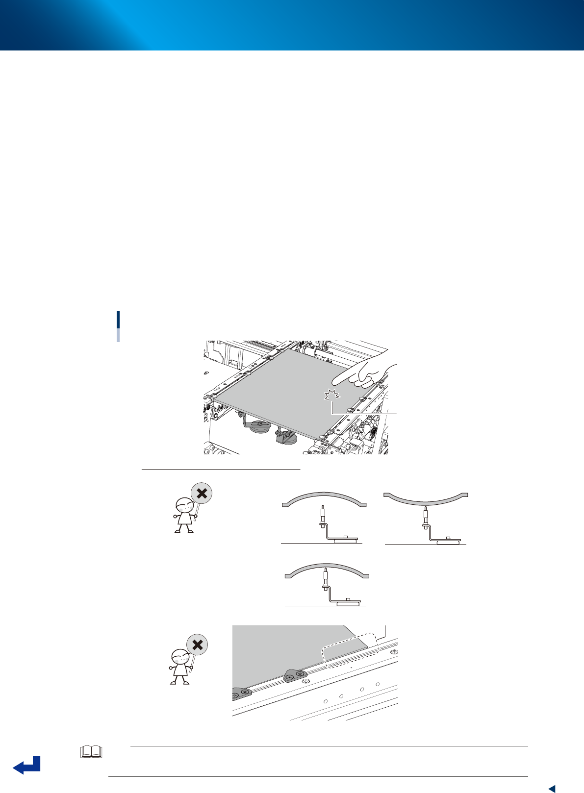
4. Knock the several points on the board lightly with the finger and visually check the board from
side to see that the push-up pins evenly support the board.
5. Visually check the board from side to see that the board doesn't warp excessively downwards
or upwards.
6. (Especially around the left and right edges of the board) Check that the board doesn't lift or
sag from the conveyor frame.
7. If it is found that the board is not clamped well by checked in 4 to 6 above, adjust the locations
of push-up pins and board hold plates or add the push-up pins to correct the condition and
recheck.
Checking the condition of clamping board.
Knock lightly on board
with fingertip
How to check the condition of clamping board
• “Board thickness” setting is incorrect.
• Locations of push-up pins are not suitable for warp of board.
• “Board thickness” setting is incorrect.
• Locations of board hold plates are incorrect.
Board edge is lifted.
23306-KMX-00
TIP
The allowable warp of component mounting boards for YRM20 is 0.5 mm or less upwards and 1.0 mm or less
downwards.

1. Flow from starting up machine to production
3-20
Chapter 3 Flow from starting up machine to production
3
Check the board is clamped on the mounting stage 2.
1. Close the upper cover and safety cover.
2. Attach the carriage to machine.
3. Release the [EMERGENCY STOP] button.
4. Press the [Convey Board] button on [Unit] - [Conveyor] screen.
5. The "Convey Boards" check screen appears. Confirm that "All position" and "Board Fix" are
ticked, and then press the [OK] button.
6. The "CONVEYOR AND FIX" message appears, then press the [OK] button twice. The board is
conveyed from the mounting stage1 of upstream to the mounting stage 2 of downstream, and
the board is fixed at its mounting position of mounting stage 2.
7. See step 2 to check the conveyor clamped condition on the downstream stage.
4
Remove the board.
1. Close the upper cover and machine safety cover.
2. Attach the carriage to machine.
3. Release the [EMERGENCY STOP] button.
4. Press the [Convey Board] button on [Unit] - [Conveyor] screen.
5. The "Convey Boards" check screen appears. Confirm that "All position" is ticked, and then
press the [OK] button.
6. The "CONVEY AND FIX" screen appears and press the [OK] button. The board is transferred
from the mounting position (mounting stage 2) to exit conveyor.
7. Remove the board manually.
1. Flow from starting up machine to production
3-21
Chapter 3 Flow from starting up machine to production
1.7 Preparing component tape (Tape feeder)
When the conveyor gets ready for operation, prepare the component tape. This procedure description in this
section assumes that the board data to be used for production has been read out.
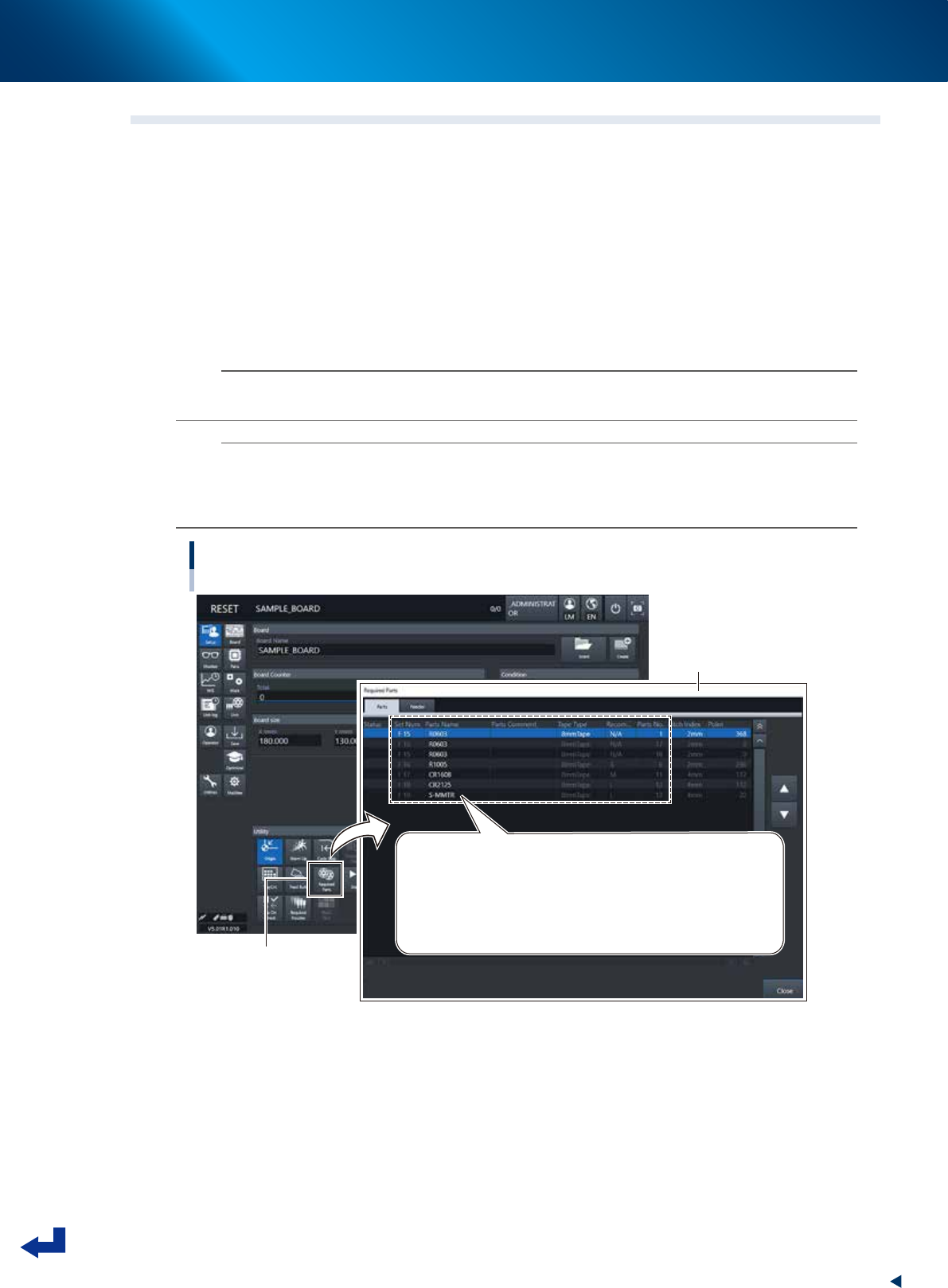
1
Open the “Required Parts” screen.
Press the [Required Parts] button and the “Required Parts” screen appears.
2
Set the feeders loaded with component tape.
The “Required Parts” screen lists the “Set Num.”, “Parts Name”, “Parts No.” and other parameters.
While observing this list, attach the feeders loaded with component tape in each corresponding
feeder set location, or attach the feeder exchange carriage to which the feeders are set, to machine.
n
NOTE
See chapter 2,"4. Preparing component tape" for the procedure to set component tape into the feeder and attach the
feeder to main machine.
n
NOTE
The component set positions (Set Num.) F1 through F64 are of the feeder exchange carriage at front side, and the F101
through F164 of the feeder exchange carriage at rear side.
P1 to P30 are the pallet numbers for the tray component supply unit at front side, P101 to P130 are the pallet numbers for
the tray component supply unit at rear side.
Preparing component tape
[Setup] screen - “Required Parts” screen
[Required Parts] button
“Required Parts” screen
Set Num. / Parts Name / Tape Type / Parts No. and other parameters appear.
Set Num. : F1 to F64 are set in the front feeder exchange carriage
F101 to F164 are set in the rear feeder exchange carriage
P1 to P30 are set in the front tray component supply unit
P101 to P130 are set in the rear tray component supply unit
24312-KMX-00