YRM20_Ope_E.pdf - 第36页
2. Operation panel and data input unit 1-5 Chapter 1 Unit names and functions 2. Operation panel and data input unit Operation panels and operation display screens for data inputs ar e provided at both the fr ont and rea…
1. Machine main unit
1-4
Chapter 1 Unit names and functions
■
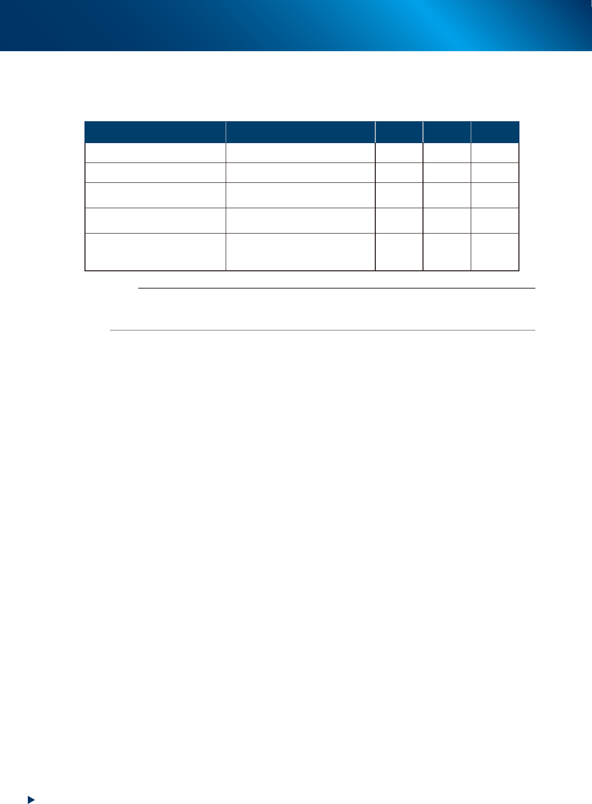
Signal light (with buzzer)
Indicates current operating conditions of the mounter with a green, yellow and red light, or green, white
and blue light explained below.
The buzzer at the top of the signal light sounds if an error or abnormal condition occurs.
Machine status Example Green
Red/
White
Yellow/
Blue
Warm-up or automatic operation ON
Emergency stop ON
System error
(with buzzer ON)
• Excessive current
• Secondary limit over
ON
Operation or board data error
(with buzzer ON)
• Pickup error, recognition error
• Data check error, etc.
ON
Components cannot be used.
• Components run out.
Tray changer door is opened.
• Non-stop exchange carriage is off.
Flashing
n
NOTE
The color coordination of signal light can be chosen upon ordering machine from "green, yellow, red" or "green, white,
blue".
The sound volume of buzzer is set as "Low" upon shipping.
■
Connection between machines (input/output signals between machines)
In most case, the mounter dose not stand alone upon its operation, but runs in "line" with pre-process/
post-process machines. The mounter ejects the finished board when it receives a signal from the machine
in the next process, and then sends a signal to the machine in the preceding process to request another
board.
The interface connector labeled "NEXT INTERFACE" connects to the machine in the next process, and
the interface connector labeled "PREVIOUS INTERFACE" connects to the machine in the preceding
process.
In the case of standard machines of right-to-left flow, the PREVIOUS INTERFACE connector is located
behind the rear right cover of the machine, and the NEXT INTERFACE connector behind the rear left
cover.
■
Feeder exchange carriage
Is a carriage dedicated to set feeders for production.
Feeders to be used in production are loaded here so they can be batch-loaded onto the mounter.
For details, see "4.2.1 Feeder exchange carriage" in this chapter.
■
Empty tape dust box
The used cut-up pieces of carrier tape are collected in the empty tape dust box.
2. Operation panel and data input unit
1-5
Chapter 1 Unit names and functions
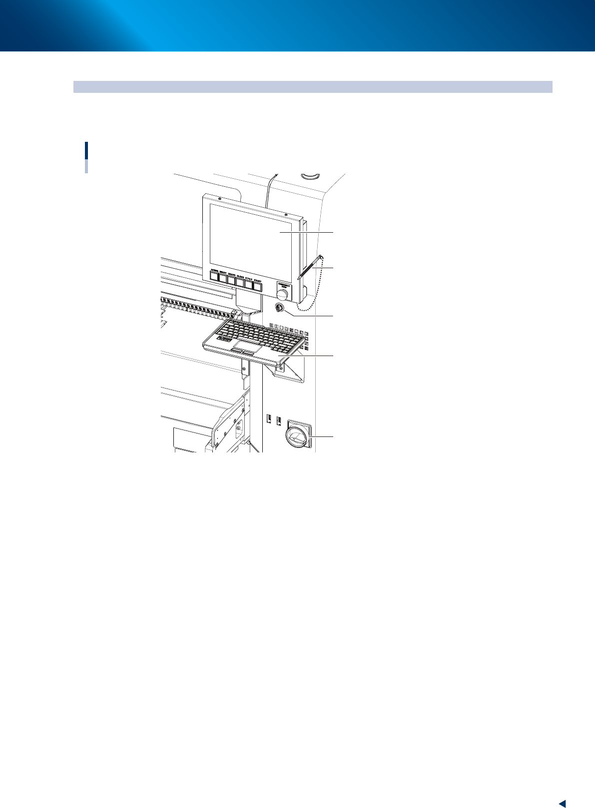
2. Operation panel and data input unit
Operation panels and operation display screens for data inputs are provided at both the front and rear
of the machine. The functions of these units are explained below.
Operation display screen
Key board
Main switch
Touch pen
Operation display screen
(Touch panel)
Feeder exchage carriage
clamp switch
23104-KMX-00
2. Operation panel and data input unit
1-6
Chapter 1 Unit names and functions
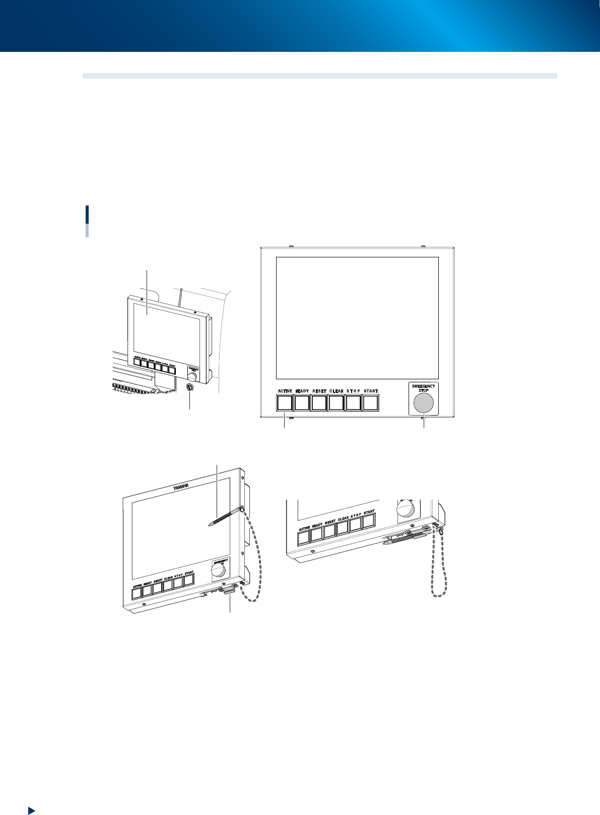
2.1 Operation display screen/Operation button
Machine operation and data editing procedures are performed at the operation display screen (touch-panel
specifications). A touch pen is used to select the onscreen buttons and parameter items. Be sure to return
the touch pen to its holder when it is not in use.
Operation button and emergency stop button are integrated to operation display screen.
These buttons play the role to operate machine, emergency stop, error clear or so, which are performed
directly by operators.
Buttons light up when machine is turned on. Moreover, lighting color of each buttons are the same as set for
signal lights.
Operation display screen / operation button
Touch pen
Touch pen holder
Operation display screen
Feeder exchage carriage
clamp switch
Emergency stop button
Operation buttons
23105-KMX-00