YRM20_Ope_E.pdf - 第149页
4. Preparing component tape 2-52 Chapter 2 Basic o pera tion 9 Reel the co ver tape to take up the slack. Pul l the cover ta pe lig htly to the a rrowed di rection and th e take-up ro ller rota tes to take up t he slac k…
4. Preparing component tape
2-51
Chapter 2 Basic operation
7
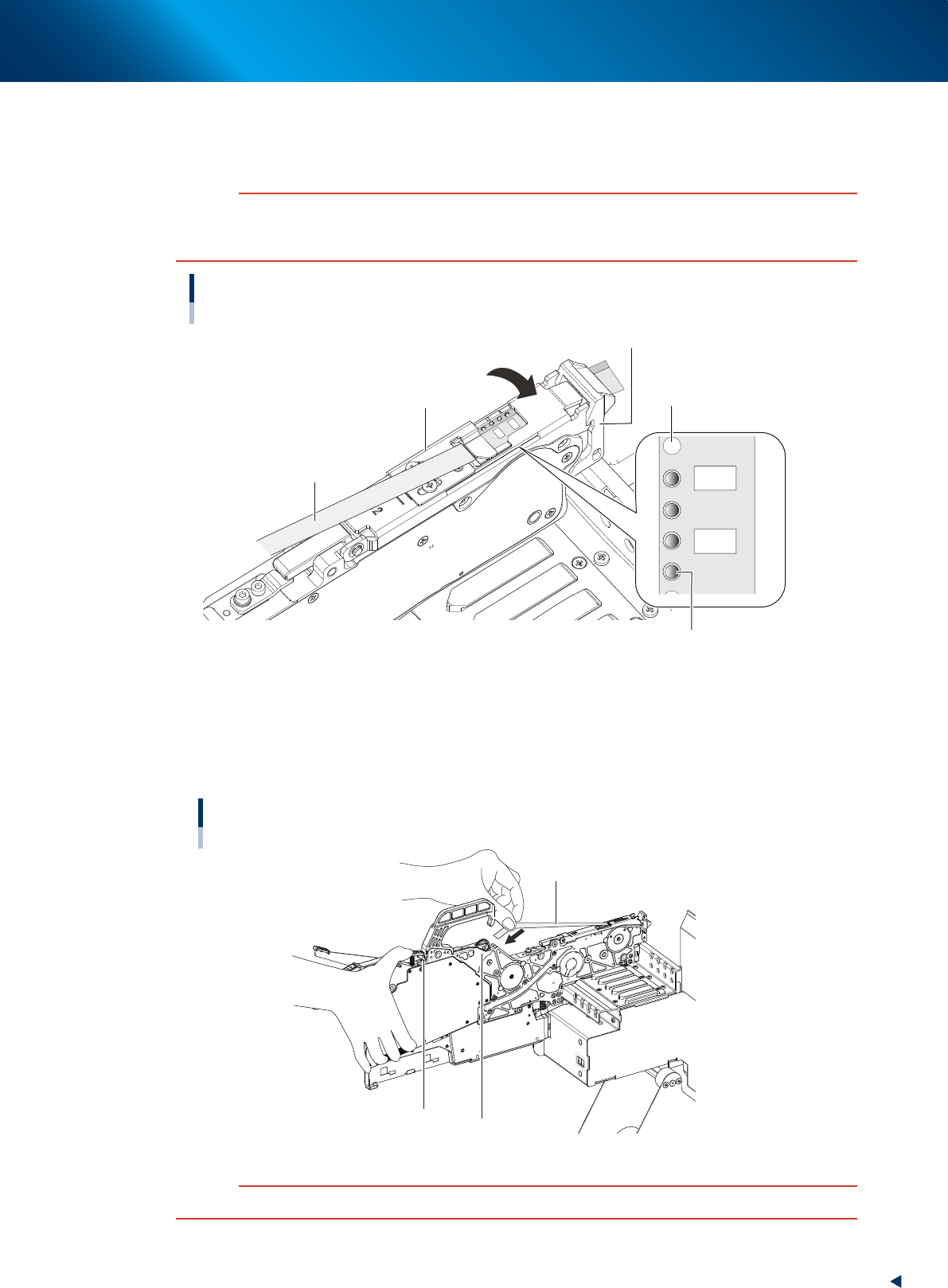
Clamp the tape guide assembly.
While confirming that the sprocket teeth bite into the carrier tape feeding hole, push down to fix the
tape guide assembly with the tape guide front lever.
c
CAUTION
Upon clamping the tape guide assembly, the squeezing of tape guide assembly into the tape guide front lever may wear
the claw of tape guide front lever. Make sure to lift up the tape guide front lever and then engage the claws of tape guide
assembly and tape guide front lever to clamp the tape guide assembly.
Clamping the tape guide assembly
Tape guide front lever
Sprocket teeth
Cover tape
Tape guide assembly
Carrier tape feeding hole
23207-KMX-00
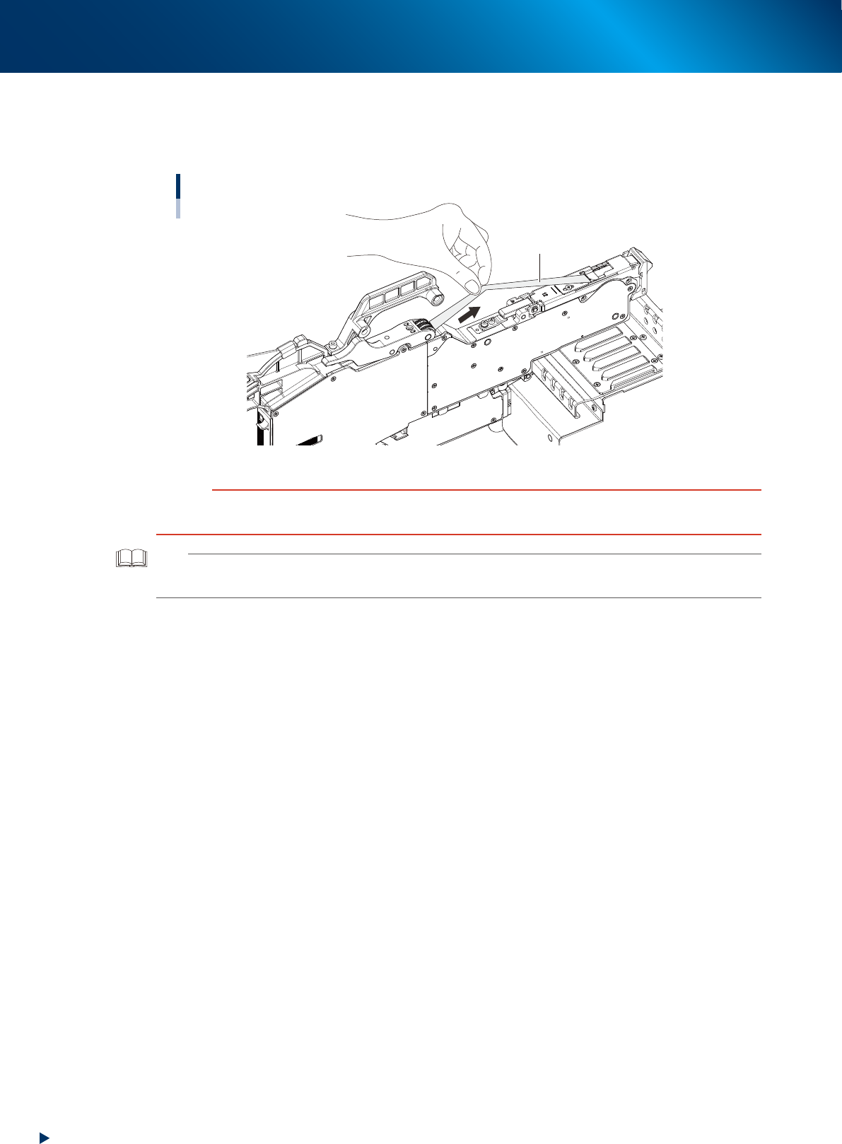
8
Set the cover tape in the take-up roller.
Push the portion of the take-up roller lever shown in the figure to make a clearance below the take-up
roller. Insert a certain amount of the cover tape into this clearance and release the take-up roller
lever to pinch the cover tape.
Setting the cover tape
Cover tape
Take-up roller
Take-up roller lever
23208-KMX-00
c
CAUTION
Check that the cover tape, extended between the take-up roller and the tape guide assembly, is not twisted.
4. Preparing component tape
2-52
Chapter 2 Basic operation
9
Reel the cover tape to take up the slack.
Pull the cover tape lightly to the arrowed direction and the take-up roller rotates to take up the slack
automatically.
Taking up the slack of the cover tape
Cover tape
23209-KMX-00
c
CAUTION
Take up the cover tape until all slacks on the cover tape removed.
During this operation, be careful not to be winded your fingers in the roller unit while taking up the cover tape.
TIP
The take-up roller performs taking up motion upon turning on the feeder.
Also, the taking up cover tape can be performed by reattaching the feeder after detaching from temporary tape set station.
4. Preparing component tape
2-53
Chapter 2 Basic operation
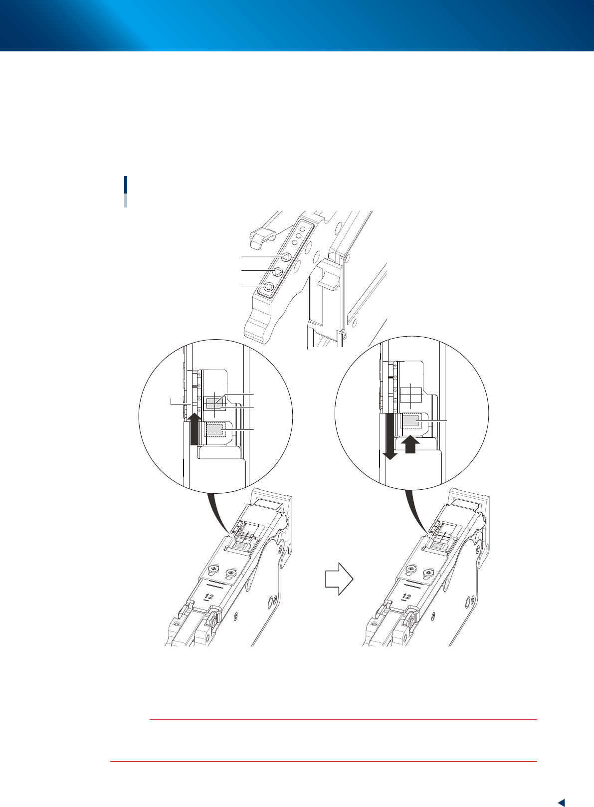
0
Align the first component with the standby position.
If pressing the [FEED] button and the [BACK] button on the feeder, the tape can be transferred or
returned with the pitch setting corresponding to the feeder type.
1. Press the [FEED] button and transfer the tape temporary to locate the first component on the
pickup position (spot: white mark or notch).
2. After pressing the component pitch and the [BACK] button once to return the component, press
the [FEED] button once and align the first component with the standby position.
Adjusting component position
[FUNC] button
[BACK] button
[FEED] button
Pickup
position
Marking
First
component
Standby
position
First
component
(Standby
position)
Press the [FEED] button to feed the
component to the pickup position.
Press the component pitch and the [BACK] button
once to return the component. Then press the [FEED]
button once and align the first component with the
standby position.
23210-KMX-00
c
CAUTION
Make sure to align the component with the standby position by the [FEED] button. Press the [BACK] button twice or more to
return the component. Then press the [FEED] button to align the component with the standby position. If aligning the
standby position by the [BACK] button, the pickup position offset of the fist component may occur.