YRM20_Ope_E.pdf - 第115页
2. Operation screen and buttons 2-18 Chapter 2 Basic operation 2. [Convey Board] button When pressing the [Convey Board] button, the following dialog box will appear . "Convey Boards" dialog box 24206-KMX-00 • …
2. Operation screen and buttons
2-17
Chapter 2 Basic operation
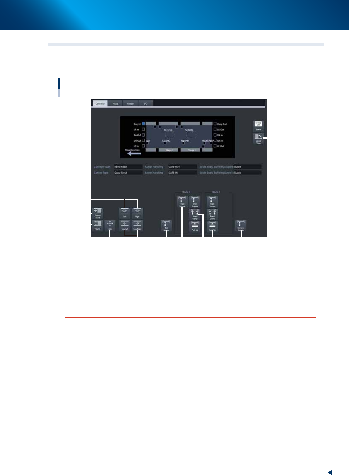
2.3 Unit screen
This section describes the manual operation buttons on the Unit screen.
█
Manual conveyor operation
[Unit] - [Conveyor] screen
Conveyor manual buttons : YRM20 Dual stage screen
2
3
5
1
6
74 8 9 10 11
24205-KMX-00
1. [Sensor Tune] button
Tunes the conveyor sensor automatically. It is not required to perform auto tuning during normal
operation. However, it is used in the case where the conveyor width is changed manually or that the
board cannot be detected correctly due to the conveyor sensor malfunction.
c
CAUTION
Make sure that no board is on the conveyor before tuning the conveyor sensor.
See the maintenance manual, chapter 3, " 2.3.1 Checking conveyor sensor condition and operation”.
2. Operation screen and buttons
2-18
Chapter 2 Basic operation
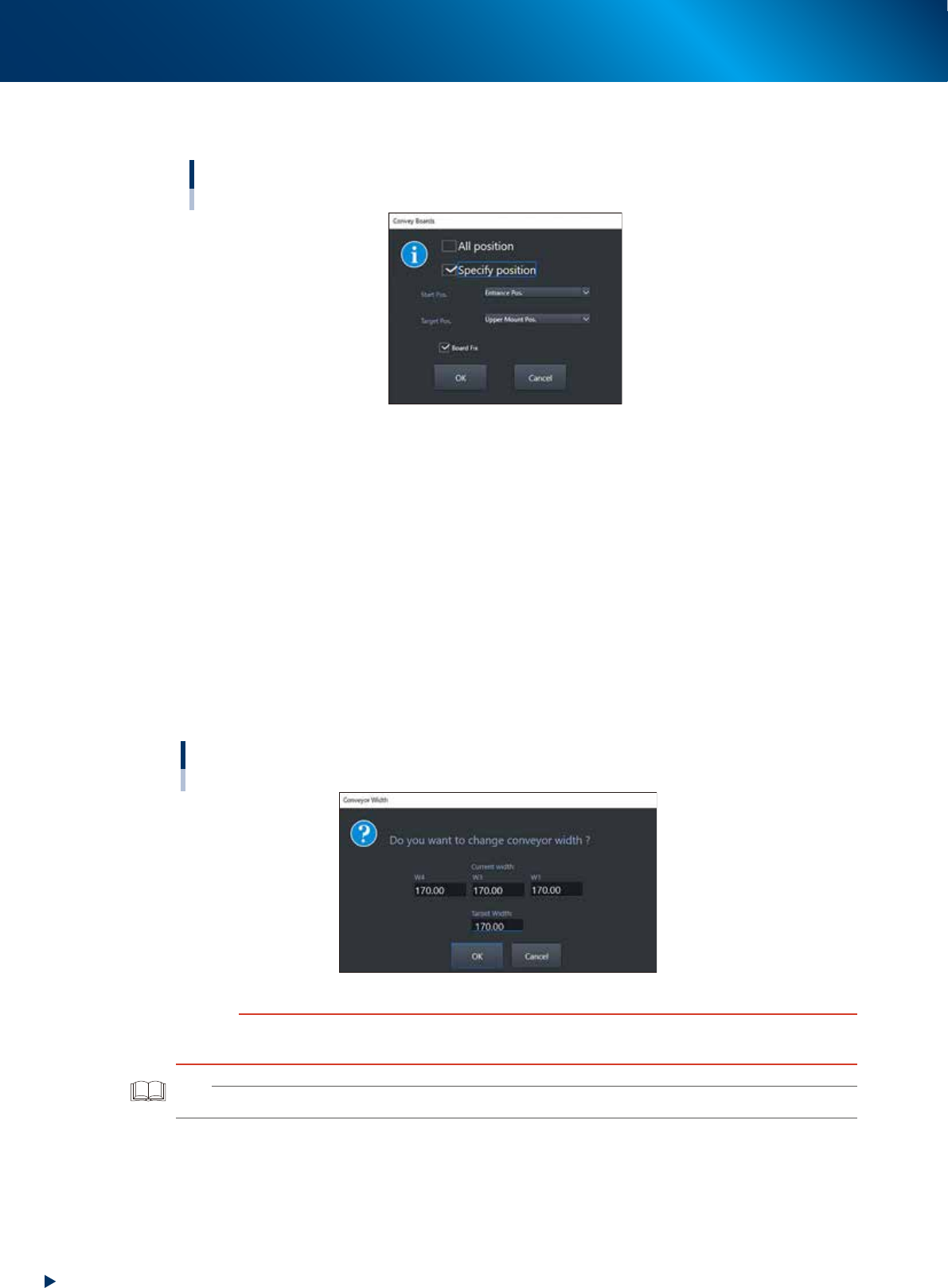
2. [Convey Board] button
When pressing the [Convey Board] button, the following dialog box will appear.
"Convey Boards" dialog box
24206-KMX-00
• All position
When selecting [All position], the board is transferred "entrance
→
Mounting stage 1", "Mounting
stage1
→
Mounting stage 2", and "Mounting stage 2
→
exit".
• Specify position
Specify one of entrance, upstream mounting position, downstream mounting position, or exit as a
start position and target position.
• Board fix
Tick the checkbox when the board is fixed after conveying board.
3. [Width] button
Use this button to adjust the conveyor width to match the width of boards to be produced.
Pressing the [Width] button displays the "Conveyor Width" screen. Check the conveyor width and
press the [OK] button. The conveyor width is changed to the specified width. The desired conveyor
width can be set by entering the value.
"Conveyor Width" screen
24207-KMX-00
c
CAUTION
When changing the conveyor width, check in advance that the conveyor rails do not collide the push-up pins and other
devices.
TIP
W1-axis and W2-axis are represented as "W1" in this screen, as they move at once.
2. Operation screen and buttons
2-19
Chapter 2 Basic operation
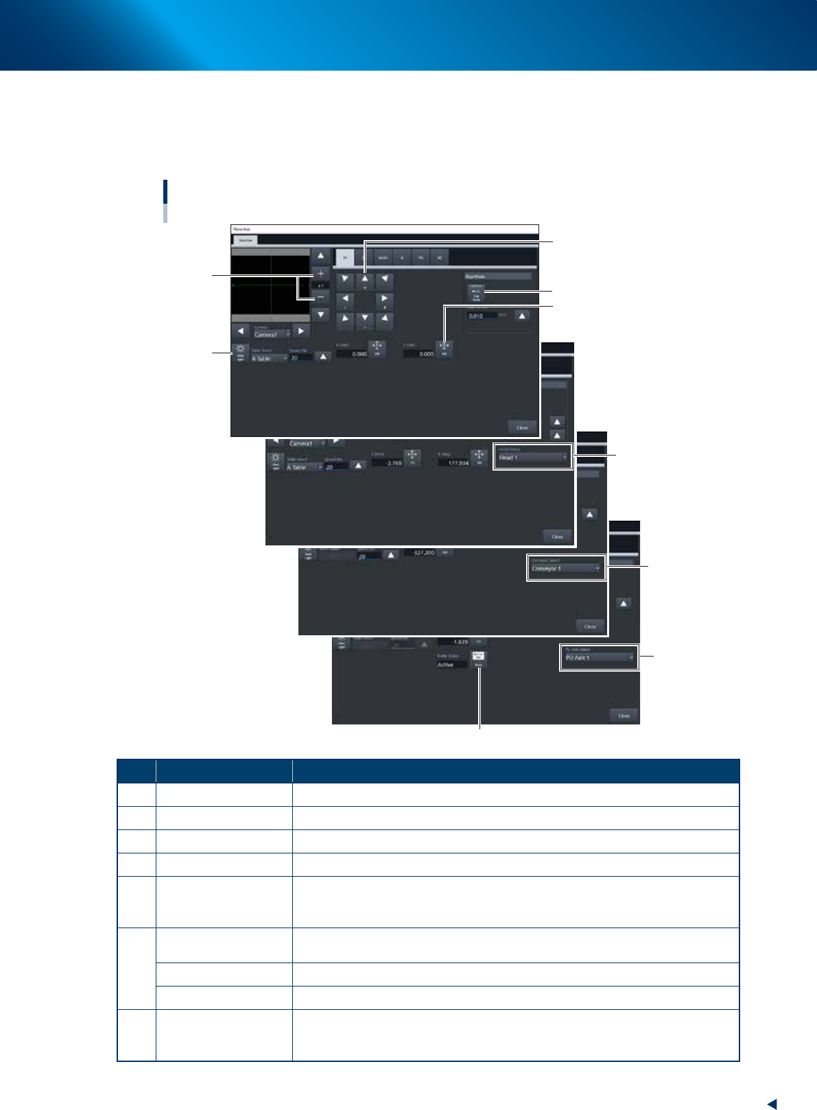
4. [Axis] button
Use this button when moving each axis manually.
Pressing the [Axis] button displays the "Move Axis" screen. Switch tabs on this screen to select the
axis to be moved. Press the [Arrow] buttons or the [PTP] button to move the axis over to the desired
position.
"Move Axis" screen
1
2
3
5
4
6
7
6
6
24208-KMX-00
Button name Function
1 Zoom in/out (+, -) Zooms in or out the image. (16 times to 1/16 times)
2 Mark Light Allows changing mark lighting manually. Using this button does not affect data.
3 PTP The object moves to the numerically input coordinate.
4 Arrow Moves the target to the desired direction. Moves quickly by long-pressing.
5 Step Mode
The inching stroke defines the distance to move when pressing an arrow button
once. With the [Step Mode] button pressed, pressing and holding an arrow button
does not stroke fast.
6
Head Select
Selects the head to be operated. (Available for operating the Z-axis and R-axis
only. Note that the several heads on the R-axis rotate simultaneously.)
Conveyor Select Selects the conveyor to be operated.
PU Axis Select Selects the PU axis to be operated.
7 Brake
Use this button when you want to release the brake during emergency stop.
(PU-axis only)
The brake is automatically released when the servo is turned on.