YRM20_Ope_E.pdf - 第126页
3. Displaying the production monitors 2-29 Chapter 2 Basic operation 3.3 Vision T he recognized image area on the screen shows the image w hen the machine recognizes a board mark, bad mark or component during the automat…

3. Displaying the production monitors
2-28
Chapter 2 Basic operation
• Cycle Time (sec/board)
The cycle time shows the average (seconds/board) of the mounting time per board. The data is updated
when the mounting is completed.
Pressing the button on the right allows to switch among “Cycle time”, “Mount CT (cycle time)” and
“Transfer CT (cycle time)”. The Cycle Time = Mount CT + Transfer CT.
The Mount CT (cycle time) includes the board mark recognition time such as fiducial bad marks,
component recognition time, mounting time, retry operation time, component discarding time and
nozzle changing times. The stopping time due to an error and the [Stop] button is not included.
• Cycle Time (sec/chip)
Shows the time (seconds) to mount one component on the board. This is the time obtained by dividing
the time for one sequence from pickup to mounting by the number of components mounted in that
sequence.
Pressing the button on the right switches the indications among “Cycle time (sec/chip)”, “Cycle time
(sec/block)”, “Cycle time (chip/hour)”, “Cycle time (block/hour)” and “Cycle time (board/hour)”.
• Working Ratio
This is the machine's independent working ratio that is not affected by the status of the upstream and
downstream machines. The following expression calculates the working ratio.
Cumulative mounting time + cumulative transfer time
(Production completion time - setup completion time) - cumulative standby time
×
100
Working ratio (%)
=
• Cumulative mounting time : Total time that head unit is operating
• Cumulative transfer time : Total transfer time (board loading/unloading)
• Cumulative standby time : Total standby time due to upstream or downstream machine
• Production completion time : Time changed to next production board
• Setup completion time : Time [START] button was pressed and operation started
• Error Stop Time
Shows the machine stop time by error. This is a period of time until the [CLEAR] button is pressed from
the error occurrence.
• [Reset] button
This resets the production control information of the production data. It resets each piece of data
displayed on the screen, current production quantity and scheduled production quantity. The "Board
Counter" value on the Setup screen is also reset when this production data is reset.
3. Displaying the production monitors
2-29
Chapter 2 Basic operation
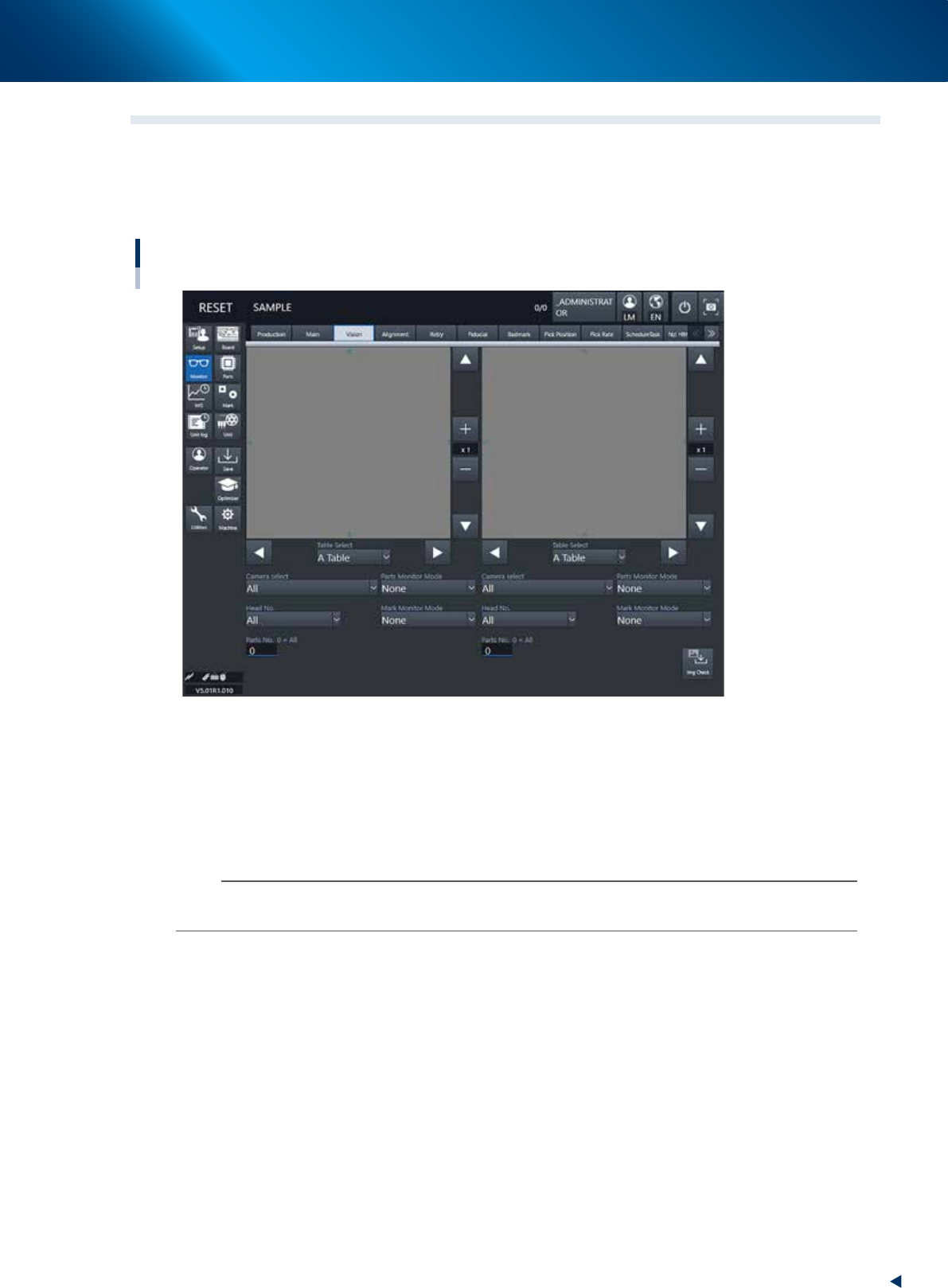
3.3 Vision
The recognized image area on the screen shows the image when the machine recognizes a board mark, bad
mark or component during the automatic operation. However, the area shows only the image of the lastly
recognized component when the high speed, continuous component recognition are performed such as by
the multi camera.
Monitor: Vision
24214-KMX-00
• Table select/ Camera select / Head No.
A desired head unit, a camera number and a head number can be selected.
• Parts number
Inputting a desired part number makes the list display only its part image. Inputting "0" shows all the
part images.
n
NOTE
An image is displayed on each left and right of the vision monitor. Select a table, a camera, a head and a part number for
each monitor so that the images can be compared with each other.
• Enlarge/reduce buttons
The recognition result image can be enlarged from 1 to 16 times by pressing the enlarge (+) button. The
image can be reduced to 1/16 by pressing the reduce (-) button. Note that when the image is enlarged,
the smooth component edges may appear jagged, and when reduced, gray sections may appear
around the edges. But this is not a fault.
• Up/down/left/right buttons
The arrow buttons on the upper right and lower right corners of the image screen move the image
vertically. The arrow buttons on the lower left and lower right of the image screen move the image left
to right or right to left. Use these arrow buttons to view a section of the image that is not displayed on
the screen.

3. Displaying the production monitors
2-30
Chapter 2 Basic operation
• Parts Monitor Mode
This specifies the mode for displaying the components on the monitor during vision recognition.
Depending on the selected item, the recognition results and detection range window will appear on the
image. This monitor mode can also be changed during operation.
• None
Displays the image taken by the camera. The recognition result values are not displayed.
• Vision Result
Displays information such as the recognition results X, Y and R direction position (pixels) and number of detection
leads. Note that the displayed items will differ according to the component recognition type.
• Detection Range
Draws a window for the component detection range. If the component does not fit within the
detection range, it will not be recognized correctly. In this case, check the pickup state or correct the
component data.
• Datum Pos.
Displays a cross cursor indicating the position used as a reference for detecting the lead or
component edge.
• Find Line
Displays the line used for component detection, on a chip component or on the component leads. If
the detection line position is incorrect, adjust the Vision parameters.
• Edge Pos
Displays a cross cursor at the lead or component edge position.
• Last Pos.
Displays a cross cursor at the center of the component.
• Binary Image
The component is displayed as a binary image.
• Mark monitor mode
This specifies the monitor display mode during mark recognition. The recognition results and binary
image will appear on the image according to the selected item. This monitor mode can be changed
during operation.
• None
Displays an image taken by the camera. The recognition result values are not displayed.
• Result
Displays the center position coordinates (pixels) of the detected mark.
• Binary Image
Displays the image taken by the camera as a binary image.
• Grey Image
Displays an image that was processed after being captured by the camera. The recognition result
values are not displayed.
• Search Result
Draws a line to indicate the boundary between the recognized mark and the background.
• Datum Circle
Draws a mark of the specified diameter from the center of the detected mark. (Possible only in
specific recognition modes.)
• Tangent Circle
Draws an inscribed circle and circumscribed circle from the center of the detected mark. (Possible
only in specific recognition modes.)