YRM20_Ope_E.pdf - 第99页
1. Before operation 2-2 Chapter 2 Basic operation 1.2 Clearing an err or If an error occurs a buzzer sounds and a warning screen appears. T o clear the error , use the following steps. 1 T urn o ff the buzzer . Press the…
1. Before operation
2-1
Chapter 2 Basic operation
1. Before operation
The following explains how to cancel emergency stop and clear errors. Read before operating the
machine.
█
Cautions during machine operation
• Do not turn off the compressed air during operation. The machine may malfunction, as pneumatic
devices are not correctly controlled.
• Before beginning maintenance, switch off the air-supply as needed. Before that, if there is the
residual pressure releasing valve, make sure to open it to release the residual pressure.
█
Cautions during power outages
If a power outage (blackout) occurs during automatic machine operation, always turn the main power
switch off to prevent faulty operation or machine damage after power has been restored. Also remove
the boards that remain in the machine.
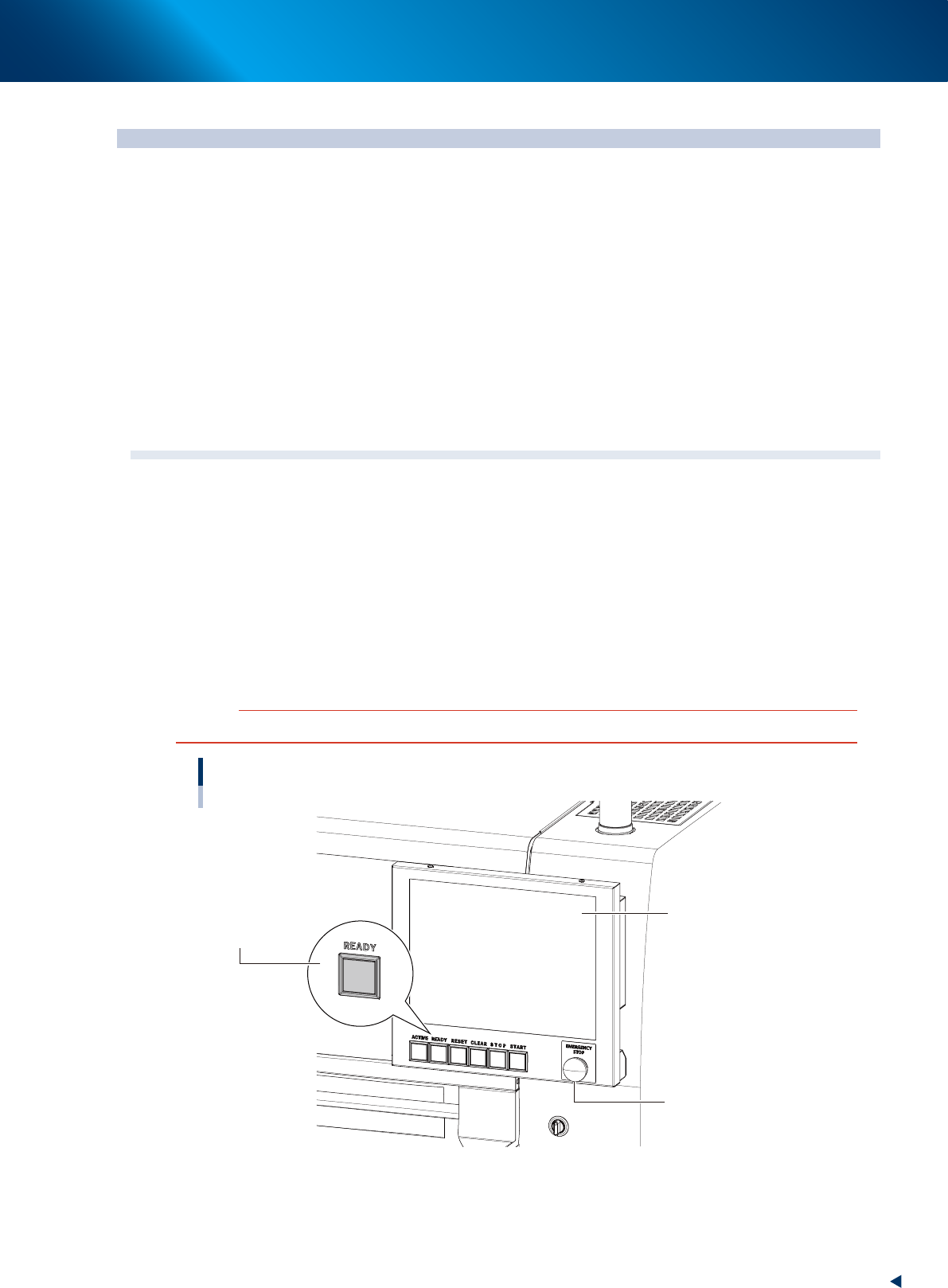
1.1 Canceling emergency stop
Follow these steps to cancel emergency stop.
1
Release the emergency stop button.
When the emergency stop button is pressed, turn it clockwise to release it.
2
Check safety.
Before continuing the procedure, check the surrounding area for safety.
3
Press the [READY] button.
Pressing the [READY] button on the operation panel turns on the servomotors.
c
CAUTION
The [READY] button is enabled only when the [ACTIVE] button next to it is active.
[READY] button
Operation display
Emergency stop button
[READY] button
23200-KMX-00
4
Check the signal light and screen display.
Check that the red lamp of the signal light is off and the emergency stop sign on the top left (status
area) of the operation screen is now off.
1. Before operation
2-2
Chapter 2 Basic operation
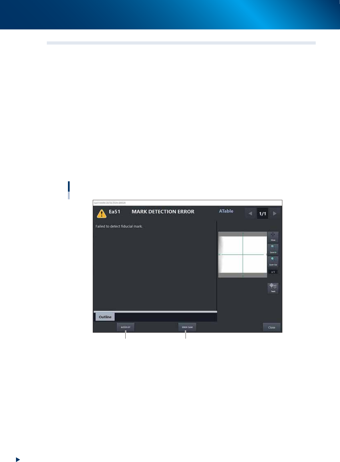
1.2 Clearing an error
If an error occurs a buzzer sounds and a warning screen appears. To clear the error, use the following steps.
1
Turn off the buzzer.
Press the [ERROR CLEAR] button on the operation panel or the [BUZZER OFF] button on the error
screen to turn off the buzzer.
2
Check the cause of the error.
Possible causes are displayed on the lower part in the error screen, so check or make a note of the
description.
3
Clear the error screen.
Press the [ERROR CLEAR] button again or the [ERROR CLEAR] button on the error screen to clear the
error screen.
4
Check the signal light and screen display.
Check that the yellow lamp of the signal light is off and the error message on the left of the status
area on the operation screen is now off.
Error screen
Mark detection error
[BUZZER OFF] button [ERROR CLEAR] button
24200-KMX-00
1. Before operation
2-3
Chapter 2 Basic operation
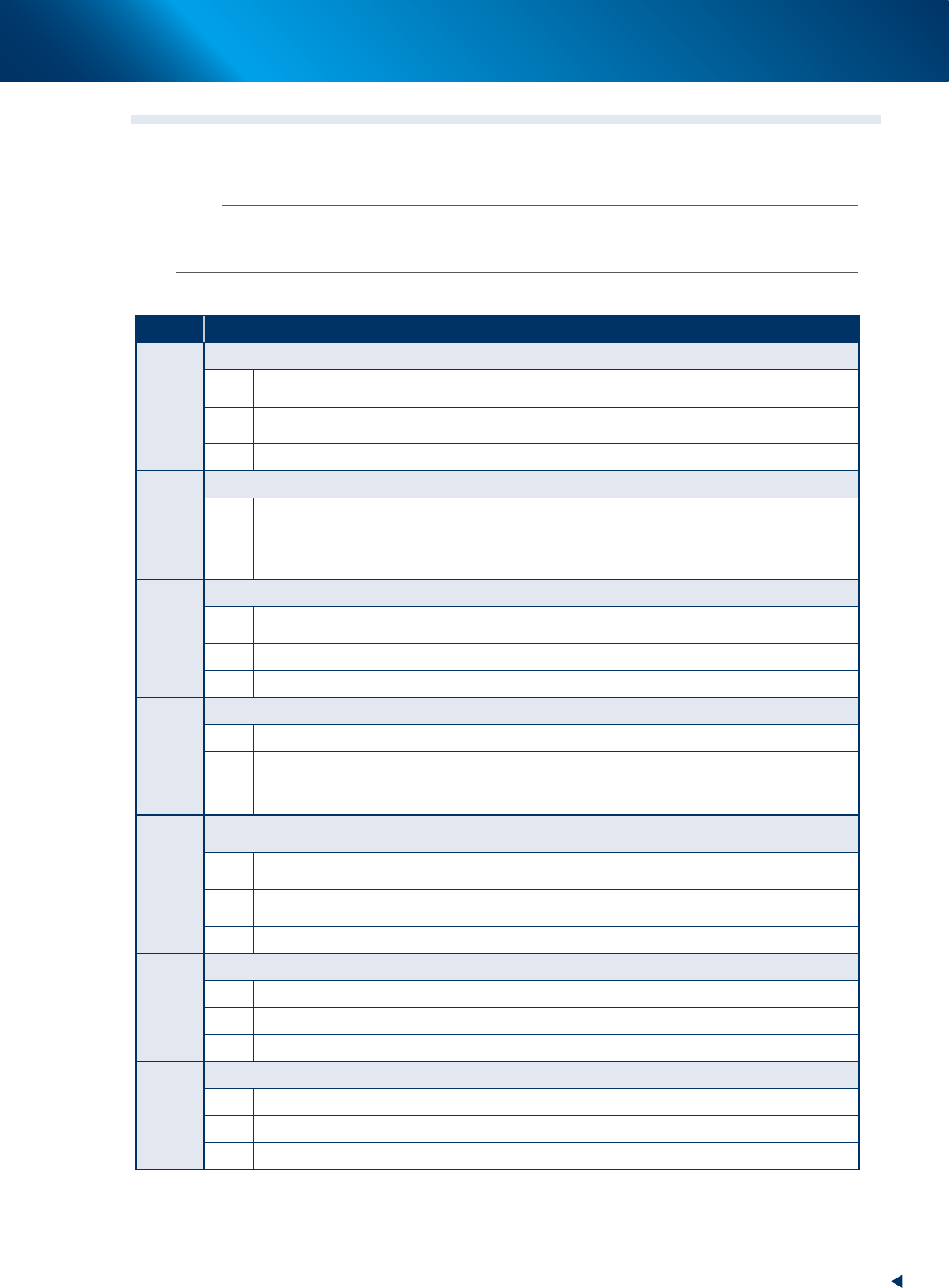
1.3 Typical errors and troubleshooting
Typical errors that might be displayed during operation are shown below along with possible causes and
corrective action.
n
NOTE
The following descriptions are extracted from the all error messages. Refer the error message list provided on YAMAHA
Service website for the messages not included here. See Appendix, "A2. YAMAHA Service website for user" about our
website.
█
Head or nozzle-related errors
Code Error name and description
Ea00097
NOZZLE RECOGNITION ERROR
State
Intensity of Component pole is not enough at threshold level. Nozzle is recognized as a component. Please
check nozzle and clean it.
Cause
Component electrode brightness did not reach the brightness ("Comp. Intensity" parameter setting) that can
be identified as a component. A nozzle might have been misrecognized as a component.
Action Check the nozzle that caused the error and clean it. Adjust the "Comp. Intensity" parameter in parts data.
Ea00204
NOZZLE STATION ERROR
State There is no nozzle present for the next sequence. Please check nozzle station data.
Cause Nozzles to be used are not specified in nozzle station information.
Action Check the settings in nozzle station information.
Ea00864
INTERLOCK ERROR
State
You can't move X ,Y ,R or W axis, because Z axis is moving or Z axis position safety sensor is OFF. Please
check Z axis position.
Cause Head is lowered or sensor is defective.
Action Raise the head (Z-axis) by hand.
Ea00865
INTERLOCK ERROR
State You can't move X or Y axis, because there isn't a nozzle station at the bottom.
Cause Nozzle station is raised, or the lower end sensor in the nozzle station does not work.
Action
Lower the nozzle station in manual mode. With the nozzle station lowered, check I/O monitor to see if the
sensor is working. If not, replace the sensor.
Ea00880
<<WARNING VACUUM LEVEL ERROR>
MOUNT IO SEQUENCE VACUUM LEVEL ERROR
State
Vacuum level has not reached the specified level. Please check the nozzle and valve condition. This may
cause bring-back cmp. or double mount problem.
Cause
Negative pressure was insufficient during component placement. A nozzle might have brought a component
back without placing it on the board.
Action Open the [Unit] – [Head] tab and immediately check the nozzles and valves.
Ea02652
INTERLOCK ERROR
State You can't move X ,Y ,R or W axis, because Z axis is not in safe position. Please check Z axis position.
Cause The head position is at a dangerous height, so the X, Y, R and W axes cannot move.
Action Raise the head to a safe height. If the machine's head has a lower end sensor, then check the sensor status.
Ea02653
INTERLOCK ERROR
State Z axis is not in a safe position. Please check Z axis position.
Cause The head position is at a dangerous height right after return-to-origin is performed.
Action Check that the current head position (Z-axis) is lowered to a dangerous height.