YRM20_Ope_E.pdf - 第72页
4. Component supply section 1-41 Chapter 1 Unit names and functions 4.2.3 Attaching/Detaching upper cover Upper cover is detac hed upon setting-up machine or maintenance w ork. T he following describes the procedure of a…
4. Component supply section
1-40
Chapter 1 Unit names and functions
█
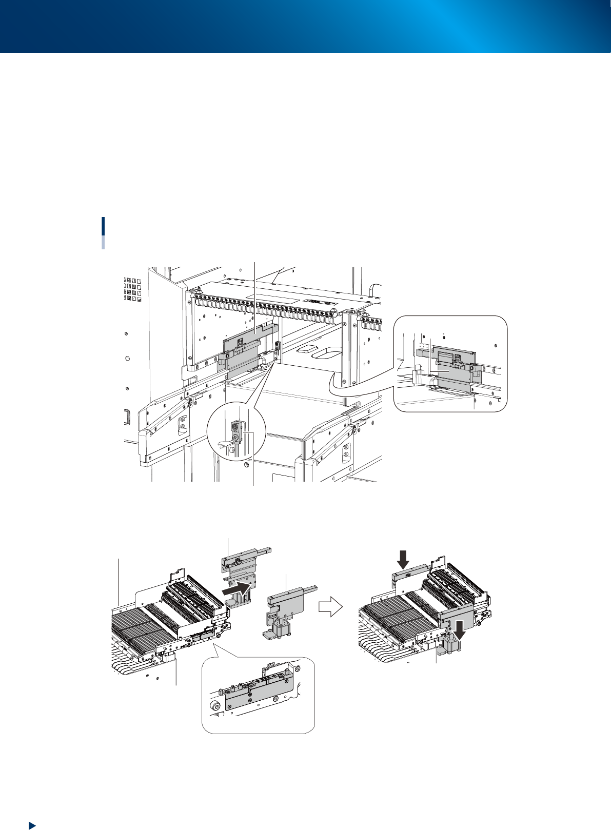
Clamp mechanism of feeder exchange carriage
The clamp mechanism of feeder exchange carriage are equipped on both sides of the carriage
attaching section of machine, and the forward end sensor at the far end of the section.
The machine recognizes with/without carriage by detecting the tip of carriage by the forward end
sensor.
The clamp switch of feeder exchange carriage is ON, while detecting the carriage by forward end
sensor and closing the machine safety cover, the clamp mechanism on both sides lowers and clamp the
carriage.
The connector is equipped at the clamp section of carriage side, and the power/air are supplied to
carriage by clamping carriage.
Clamp mechanism of feeder exchange carriage
Forward end sensor
Clamp mechanism of carraige
(on the right side)
Clamp mechanism of carraige (on the left side)
Clamp mechanism of carraige
(on the right side)
Clamp mechanism of carraige (on the left side)
Carriage clamping connector
(on the right side)
• Clamping motion of carriage
Feeder exchange carriage
23125-KMX-00
4. Component supply section
1-41
Chapter 1 Unit names and functions
4.2.3 Attaching/Detaching upper cover
Upper cover is detached upon setting-up machine or maintenance work.
The following describes the procedure of attaching/detaching upper cover.
█
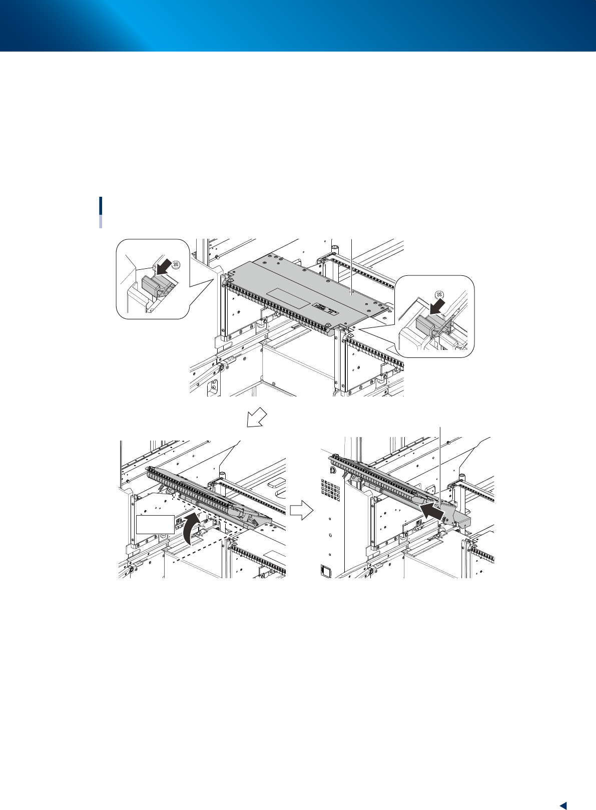
Detaching upper cover
1. Pull frontward the cover locks located at both sides of upper cover.
2. Open the upper cover 30 degrees upward by hand.
3. Pull out front-and-upward while supporting the upper cover with both hands.
Detaching upper cover
Pull out front-and-upward
30 deg.
Upper cover
Cover lock
Cover lock
23126-KMX-00
4. Component supply section
1-42
Chapter 1 Unit names and functions
█
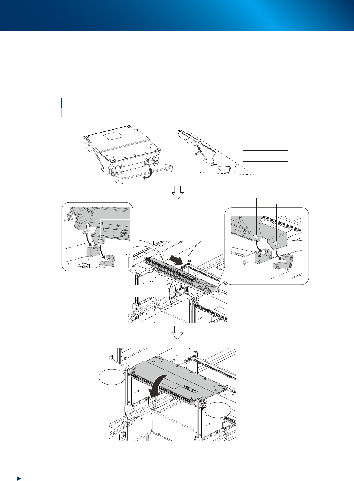
Attaching upper cover
1. Open upper cover
end
plate manually and hold position of upper cover guide section and end plate
as illustrated below (angle 30 degrees).
2. Insert upper cover into machine at an angle of 30 degrees. At this time, make far end pins and
second far end pins, located at both sides of upper cover, fit into their guides.
3. Close upper cover and confirm the cover locks at both sides click.
Approx. 30 degs.
Attaching upper cover
Approx. 30 degs.
■ Side view
Upper cover guide section
CLICK !
CLICK !
Far end pin (left)
Far end pin (right)
Second far end pin (right)
Second far end pin (left)
Upper cover end plate
23127-KMX-00