YRM20_Ope_E.pdf - 第31页
4.4 Non-stop feeder change 1-46 Feeder remo ving conditions : 1. Setting "Skip Retr y" 1-48 Feeder remo ving conditions : 2. Pressing [Feeder Remo ve] butt on 1 -49 Feeder remo ving conditions : 3. Setting alt …

Chapter 1 Unit names and functions
Contents
1. Machine main unit 1-1
2. Operation panel and data input unit 1-5
2.1 Operation display screen/Operation button 1-6
2.2 Keyboard (option) 1-8
2.3 Other connection ports 1-9
3. Head unit 1-10
3.1 Component pick-and-place head 1-11
3.1.1 RM Head unit 1-11
3.1.2 HM Head unit 1-13
3.2 Nozzle types 1-14
3.3 Nozzle station (option) 1-16
3.3.1 Overview of Nozzle station 1-16
3.3.2 Nozzle holder 1 and 2 1-17
3.3.3 Type A nozzle holder 1-18
3.3.4 Type B nozzle holder 1-19
3.3.5 Attaching/Detaching nozzle holder 1-20
3.4 Blow station 1-22
3.4.1 Shaft-blow function 1-22
3.4.2 Manual nozzle shaft blow procedure 1-23
3.4.3 Automatic nozzle shaft blow procedure 1-28
3.4.4 Shaft blow dump of very small components 1-31
3.5 Vacuum pump ( RM head) 1-32
3.5.1 Vacuum pump (RM head) 1-32
4. Component supply section 1-33
4.1 Machine layout 1-33
4.2 Supplying component tape 1-35
4.2.1 Feeder exchange carriage 1-35
4.2.2 Feeder exchange carriage attaching section of machine 1-38
4.2.3 Attaching/Detaching upper cover 1-41
4.3 One-stop cover (option) 1-45

4.4 Non-stop feeder change 1-46
Feeder removing conditions : 1. Setting "Skip Retry" 1-48
Feeder removing conditions : 2. Pressing [Feeder Remove] button 1-49
Feeder removing conditions : 3. Setting alternative component function 1-50
5. Conveyor 1-53
5.1
Conveyor unit 1-53
5.2 Sensor layout of conveyor unit 1-55
5.3 Board position in machine by board size 1-57
6. Recognition unit 1-58
6.1 Fiducial, Scan and Side-view camera 1-58
6.2 Side-view function (Scan camera / Side-view camera) 1-60
6.3 Multi-view cameras 1-61
7. Axis configuration 1-62
7.1 Head unit axis configuration 1-62
7.1.1 RM head unit 1-62
7.1.2 HM head unit 1-63
7.2 Main axis and conveyor axis configuration 1-64
1. Machine main unit
1-1
Chapter 1 Unit names and functions
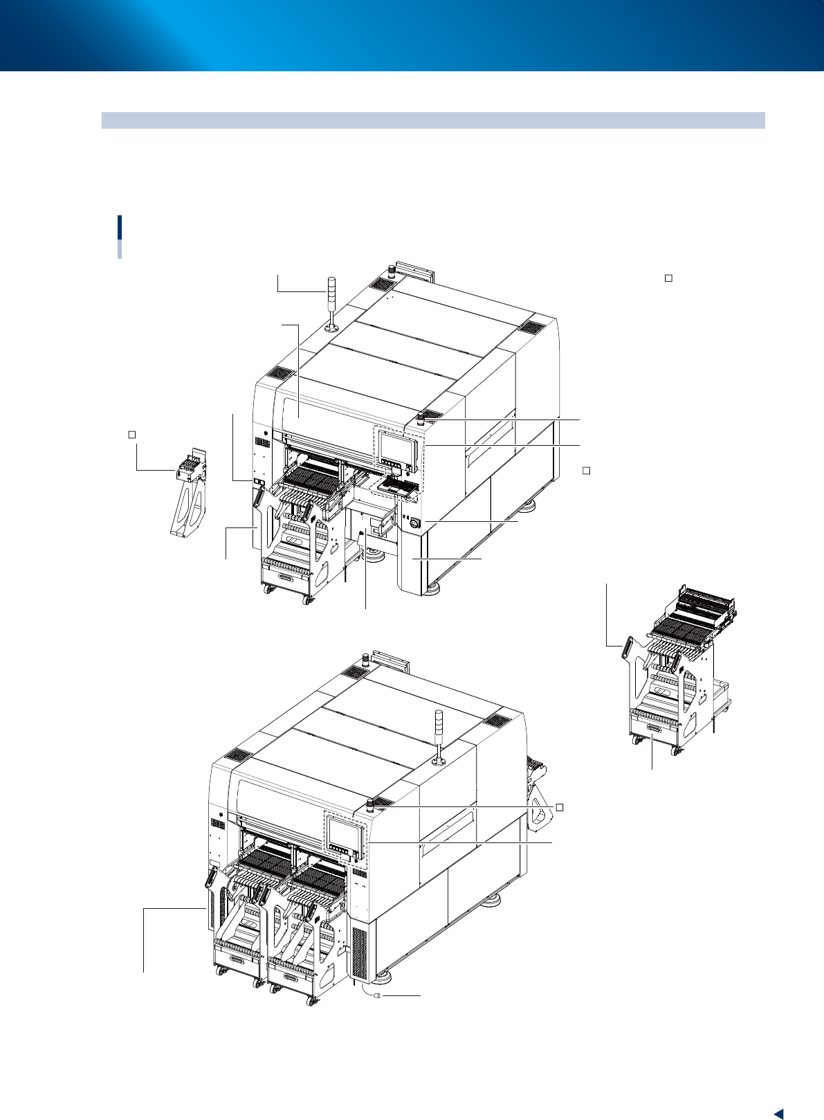
1. Machine main unit
Here describes names and functions of major parts of the machine main unit (hereinafter referred to as
machine).
A standard machine has the following configurations after installation is complete.
■ Safety cover
Front
Rear
■ Operation panel and
data input unit
Machine main unit
■ :
Standard units
: Options
Keyboard
Set-up station
Component supply indicator
■ Main switch
■ Power connection terminals
■ Feeder exchange carriage
■ Empty tape dust box
■ Tape cutter
(cover inner side)
■ Pressure gauge
■ Air connection port
■ Operation panel and
data input unit
(rear side)
■ Component supply indicator
■ Signal light
■ Connection between
machines
(panel inner side)
■ Connection between machines
23100-KMX-00