YRM20_Ope_E.pdf - 第86页
5. Conveyor 1-55 Chapter 1 Unit names and functions 5.2 Sensor layout of conveyor unit T he following sho ws the sensor and stopper lay out of the conv eyor unit. Conveyor sensor layout for YRM20 Right-to-left flow examp…

5. Conveyor
1-54
Chapter 1 Unit names and functions
4. Exit stopper
When the machine in downstream doesn't demand a board, the mounted board waits at the position of
the exit stopper.
5. Push-up plate
6. Push-up pins
Push-up pins are arranged on the push-up plate depending on the spec and shape of board to be
mounted. When a board comes to the mounting position, the push-up plate raises and the push-up pins
secure the board by pushing it up from the bottom.
7. Board hold plate
8. Board clamp plate (clamp board assembly)
When a board comes to the mounting position, also the board clamp plate raises.
This clamps the board by pushing its edges up against the board hold plates.
The position of board hold plate varies depending on spec and shape of a board.
9. Pin push-up prevention sensor
This sensor stops the push-up plate raising motion by detecting the push-up pin pushing up the conveyor
frame, even when a push-up pins are placed between the push-up plate and the conveyor frame.
n
NOTE
YRM20 is specified only for the dual stage model above.
The whole mounting stage 2 of conveyor unit of dual stage machine moves back and forth (U-axis).
The mounting time can be shortened by the above motion as the mounting position, component pick-up position and head
unit come close each other.
5. Conveyor
1-55
Chapter 1 Unit names and functions
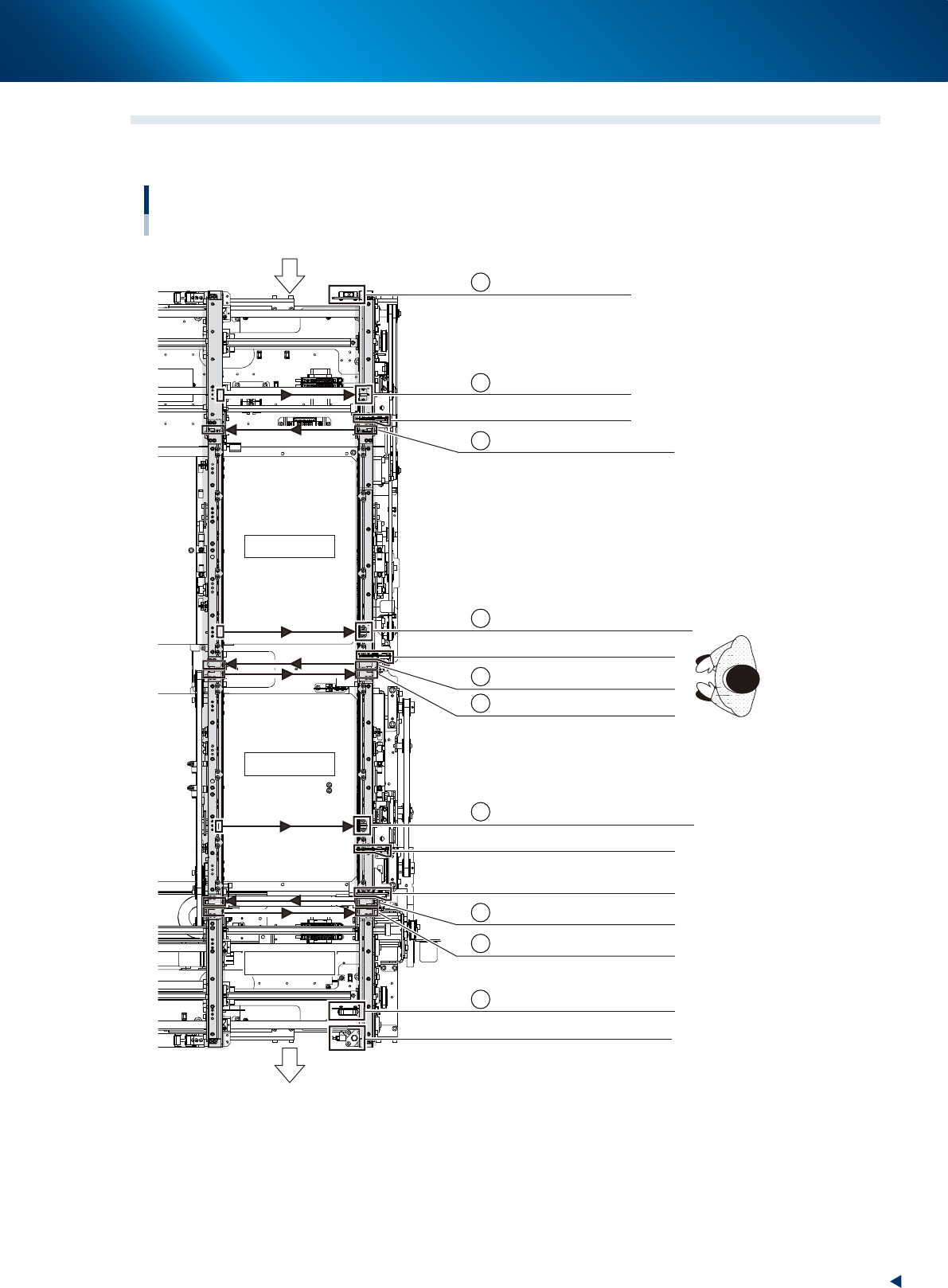
5.2 Sensor layout of conveyor unit
The following shows the sensor and stopper layout of the conveyor unit.
Conveyor sensor layout for YRM20
Right-to-left flow example
Mounting stage 1
Mounting stage 2
Exit conveyor
Carrying direction
CONVEYOR ENTRANCE
WAITING POSITION
Entrance stopper
Stage 1 main stopper
Exit stopper
STAGE 1 TRANSIT DETECTION SENSOR
STAGE 2 ENTRANCE
STAGE 1 EXIT
STAGE 1 MOUNTING POSITION
EXIT CONVEYOR ENTRANCE
EXIT POSITION
A
B
C
D
E
F
G
H
I
J
STAGE 2 MOUNTING POSITION
Stage 2 main stopper 1
Stage 2 main stopper 2
STAGE-2 EXIT
23133-KMX-00
5. Conveyor
1-56
Chapter 1 Unit names and functions
Sensor name Sensor number Remarks
A CONVEYOR ENTRANCE N0314000 Reflective type
B WAITING POSITION N0314001 Thrubeam type
Entrance stopper
T0100053
C STAGE-1
TRANSIT DETECTION SENSOR
N0314006 Thrubeam type
D STAGE-1
MOUNTING POSITION
N0314004 Thrubeam type
STAGE-1
main stopper
T0100054
E STAGE-1 EXIT N0314005 Thrubeam type
F STAGE-2 ENTRANCE N31C000 Thrubeam type
G STAGE-2 MOUNTING POSITION N31C001 Thrubeam type
STAGE-2
main stopper1
T0100061
STAGE-2
main stopper2
T0100062
H STAGE-2
EXIT N031C002 Thrubeam type
I
EXIT CONVEYOR
ENTRANCE N031C004 Thrubeam type
J EXIT POSITION N031C006 Reflective type
Exit
stopper
T0100063
n
NOTE
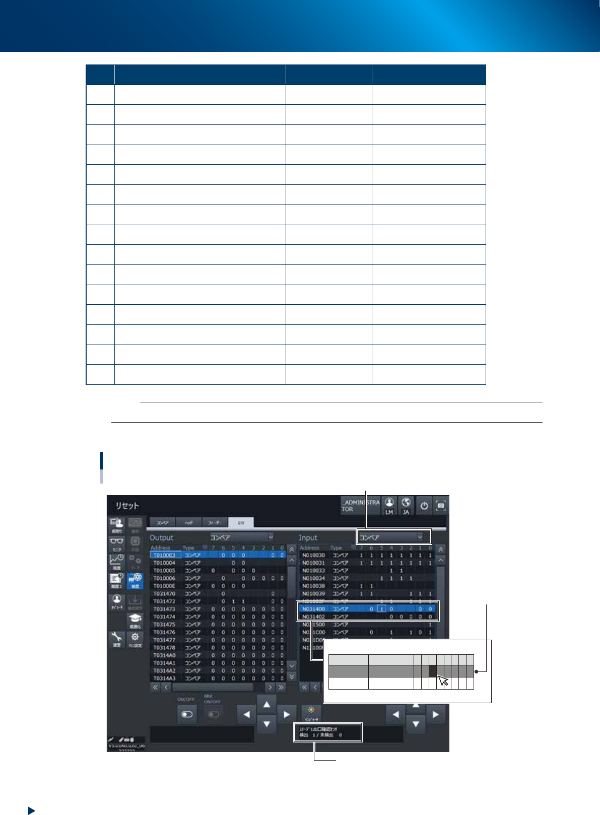
The condition of conveyor sensors can be checked in [Unit] - [I/O] screen.
►
How to check the sensor addresses
Address
N031400
N031402
Type
CONVEYOR
CONVEYOR
7 6
0
5
1
4
0
0
3
0
2
0
1
0
0
0
0
0
Conveyor sensors : Check the sensor number and I/O
[Unit] - [I/O] screen
1. Select "CONVEYOR" in pull-down list of "Input".
3. Check the sensor recognition condition
ex. STAGE-1 EXIT
DETECT 1 / NOT DETECT 0
The current condition of
the sensor is displayed
with "1" or "0".
2. Select a target address.
ex. N0314005 STAGE-1 EXIT
24118-KMX-00