YRM20_Ope_E.pdf - 第153页
4. Preparing component tape 2-56 Chapter 2 Basic o pera tion w Cu t the carrie r tape. Before setting the tape feeder on the machi ne, feed the tape out until a com ponent is at the pickup position, the n cut the carrier…
4. Preparing component tape
2-55
Chapter 2 Basic operation
q
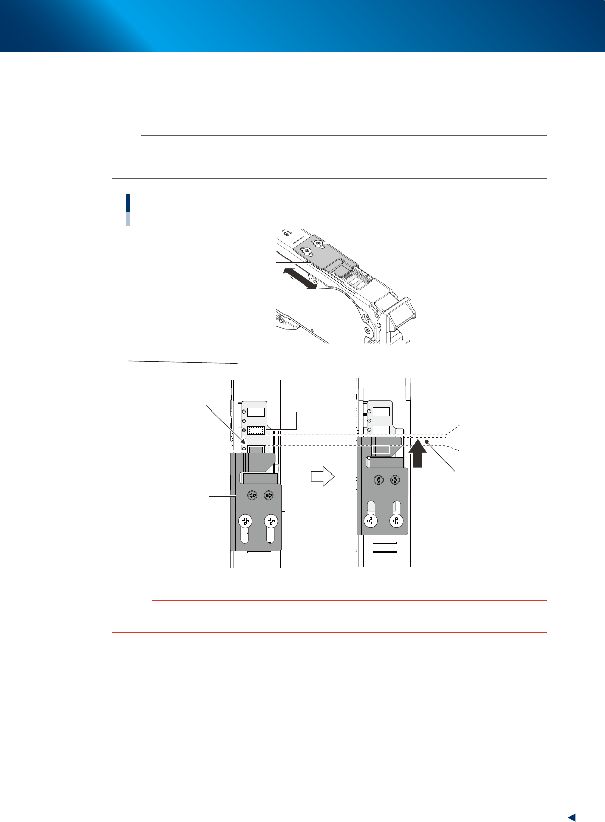
Check and adjust the tape support plate position.
If the feeder type is 12 mm or wider, it is required to adjust the tape support plate according to the
components shape. Adjust the tape support plate position by loosening the 2 adjustment screws with
Phillips screwdriver. Locate the tape support plate between A and B illustrated below (closer to A).
n
NOTE
The cover tape is required to be adjusted upon changing the tape support plate position. When the cover tape shortens,
push the take-up roller lever, as the same procedure of Step 8, and pull out cover tape from take-up roller. When some
slack is on cover tape, remove it.
Adjusting tape support plate position
Not supported appropriately
Pickup pocket
(Component pickup
position)
Standby position pocket
(Component standby position)
A. Front side of
pickup pocket
B. Rear side of
stanby position pocket
Place the leading edge of
tape support plate at rear side
of the center of A and B
Adjusting tape support plate
Slide the tape support plate
Tape support plate
Tape support plate
Adjustment screw
23211-KMX-00
c
CAUTION
If the tape support plate is not adjusted, the components may pop out after removing the cover tape, or its pickup position
may get unstable.
4. Preparing component tape
2-56
Chapter 2 Basic operation
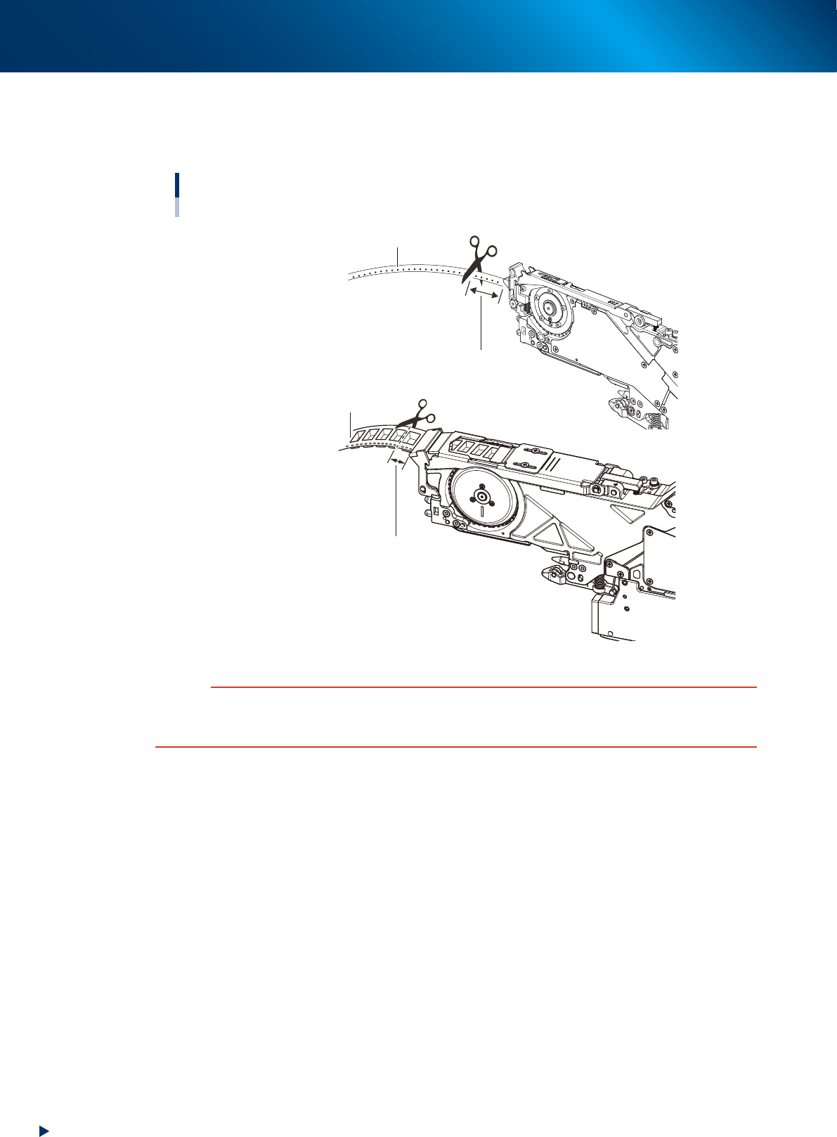
w
Cut the carrier tape.
Before setting the tape feeder on the machine, feed the tape out until a component is at the pickup
position, then cut the carrier tape about 15 mm from the feeder tip.
Cutting the carrier tape
■ 12 mm or wider feeder
Carrier tape
Cut straight the carrier tape
at about 15 mm from the feeder tip.
Cut straight the carrier tape
at about 15 mm from the feeder tip.
Carrier tape
■ 8 mm feeder
23212-KMX-00
c
CAUTION
If using the carrier tape without cutting the excess component, it could block the path way for discharging the tape.
Cutting a hard emboss tape too short causes the carrier tape to touch at the machine slope entrance, then the feeding
trouble may occur.
4. Preparing component tape
2-57
Chapter 2 Basic operation
4.1.2 Setting feeders on the feeder exchange carriage
This section describes the procedure to set the feeder with component tape on the feeder exchange carriage
using ZSR feeder as example.
c
CAUTION
Always use a temporary tape set station or a power station for the off-line setup to set the tape. Make sure to prevent
essentially to set tape on tape feeder on feeder exchange carriage already attached to mounter, as a component tape may
fall inside of mounter upon working.
n
NOTE
The 4 types of tape feeder are provided and applicable for YRM20; ZSR feeder, ZS feeder, auto loading feeder, and SS
feeder. Though some limitation occur upon using SS feeder.
See "4.2 SS Feeder" for details.
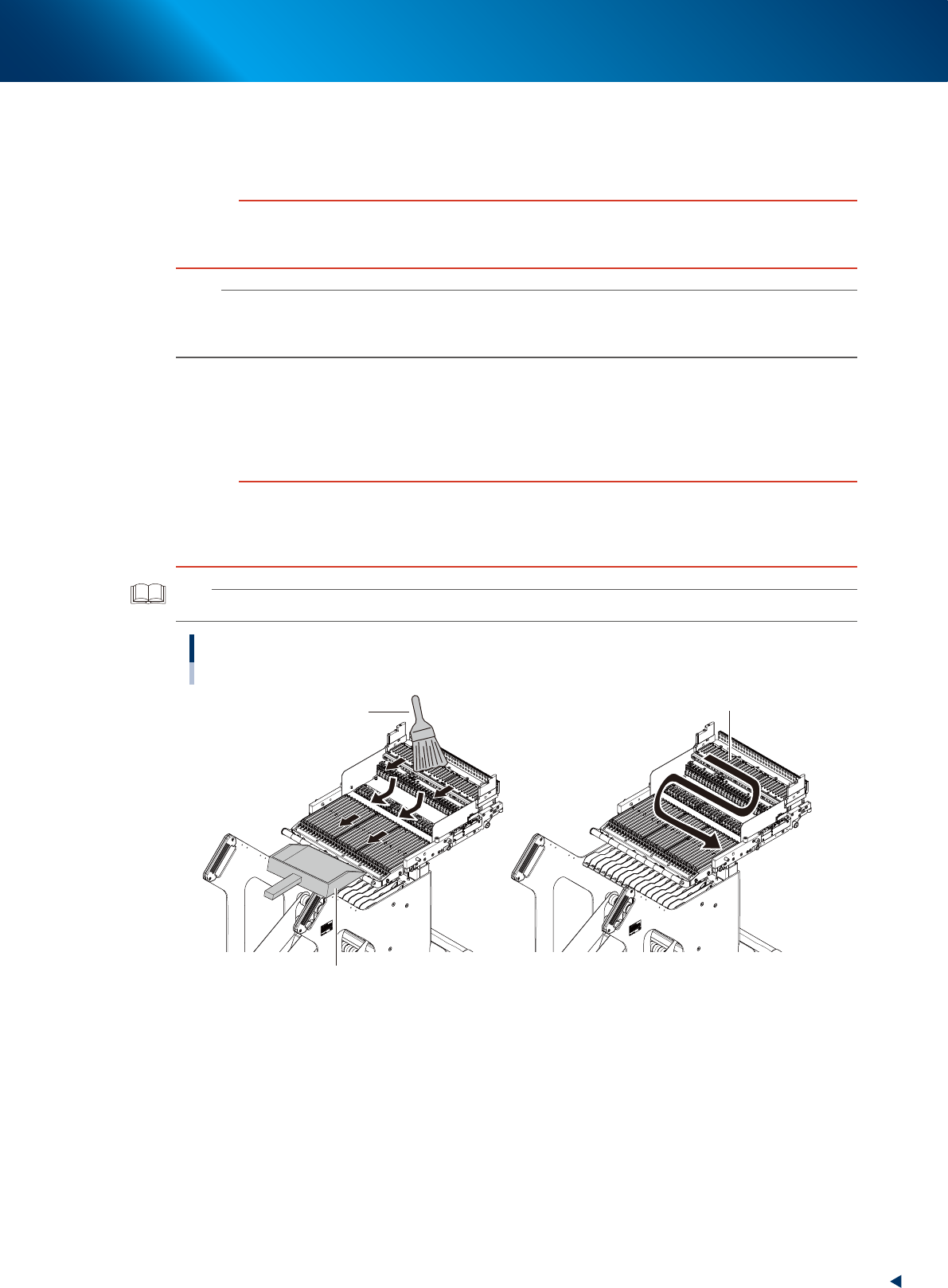
1
Clean the feeder plate.
Before setting the feeder on the carriage, remove dust or foreign matter from the feeder plate. Use
the feeder plate cleaning brush that comes with the machine, a vacuum cleaner (home use) or the
vacuum assembly (option) to get rid of dust or foreign matter on the feeder plate.
c
CAUTION
If a component or foreign matter disturbs when setting a feeder to carriage, the feeder may not sit there correctly, making
it unable to pick up components in a stable manner.
Foreign object where the feeder sits in may cause electrical short circuit, possibly causing devices to be damaged. When
cleaning the feeder plate, be sure not to let foreign object contaminate the connectors.
TIP
The air joint equipped in feeder exchange carriage can be actuated only when the carriage is attached to mounter.
Cleaning feeder plate for carriage
Use home vacuum cleaner.
Cleaning brush
Use dust pan to collect foreign objects.
23213-KMX-00