YRM20_Ope_E.pdf - 第147页
4. Preparing component tape 2-50 Chapter 2 Basic o pera tion ► Edge delamination 12 mm, 16 mm and 24 mm tape guides can be used without passing the cover tape into the notch of the tape guide assembly . This method is ca…
4. Preparing component tape
2-49
Chapter 2 Basic operation
4
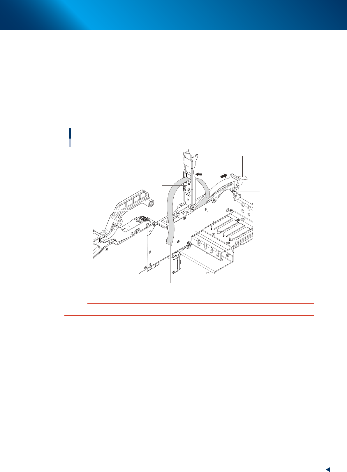
Peel off the cover tape.
The tape is in two layers – one called “carrier tape” that contains the components and the other
called “cover tape” that covers the components on the top. Remove the leading portion of the cover
tape in advance to the extent that the tape reaches the winding roller.
5
Set the carrier tape.
Run the carrier tape through the hole in the tape guide front lever.
6
Set the cover tape.
Run the cover tape through the notch in the tape guide assembly (or tape support plate). Be sure to
peel off enough length of tape so the cover tape reaches the take-up roller.
Carrier tape and cover tape
Example: ZS feeder (12mm)
Tape guide front lever
Tape guide assembly
Cover tape
Take-up roller
Carrier tape
Tape support plate
23205-KMX-00
c
CAUTION
When running the tape through the unit, be careful not to deform the tape guide assembly with excessive force.
4. Preparing component tape
2-50
Chapter 2 Basic operation
►
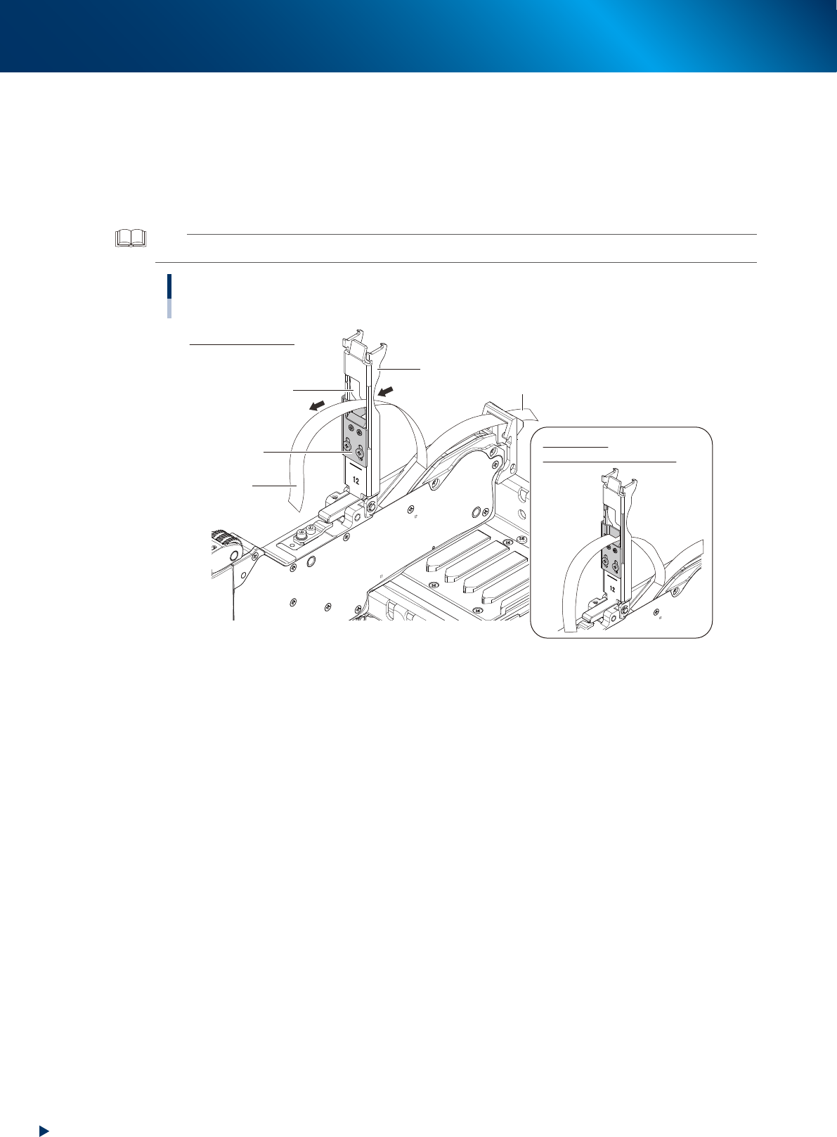
Edge delamination
12 mm, 16 mm and 24 mm tape guides can be used without passing the cover tape into the notch
of the tape guide assembly. This method is called "Edge delamination".
Generally the edge delamination has the advantages that cutting down the component waste, or
priventing scratch on component surface (caused by deformed tape guide assembly or so). Though,
as the static cling of component may cause pickup error, YAMAHA recommend "delamination in
advance" which runs tape through the notch.
TIP
The tape support plate of 32mm or larger ZS feeder does not have notch, only the edge delamination is available.
Edge delamination
12mm ZS feeder
Tape support plate
Edge delamination
Normal case
Cover tape insertion slot
Carrier tape
Tape guide assembly
Cover tape
(Delamination in advance)
23206-KMX-00
4. Preparing component tape
2-51
Chapter 2 Basic operation
7
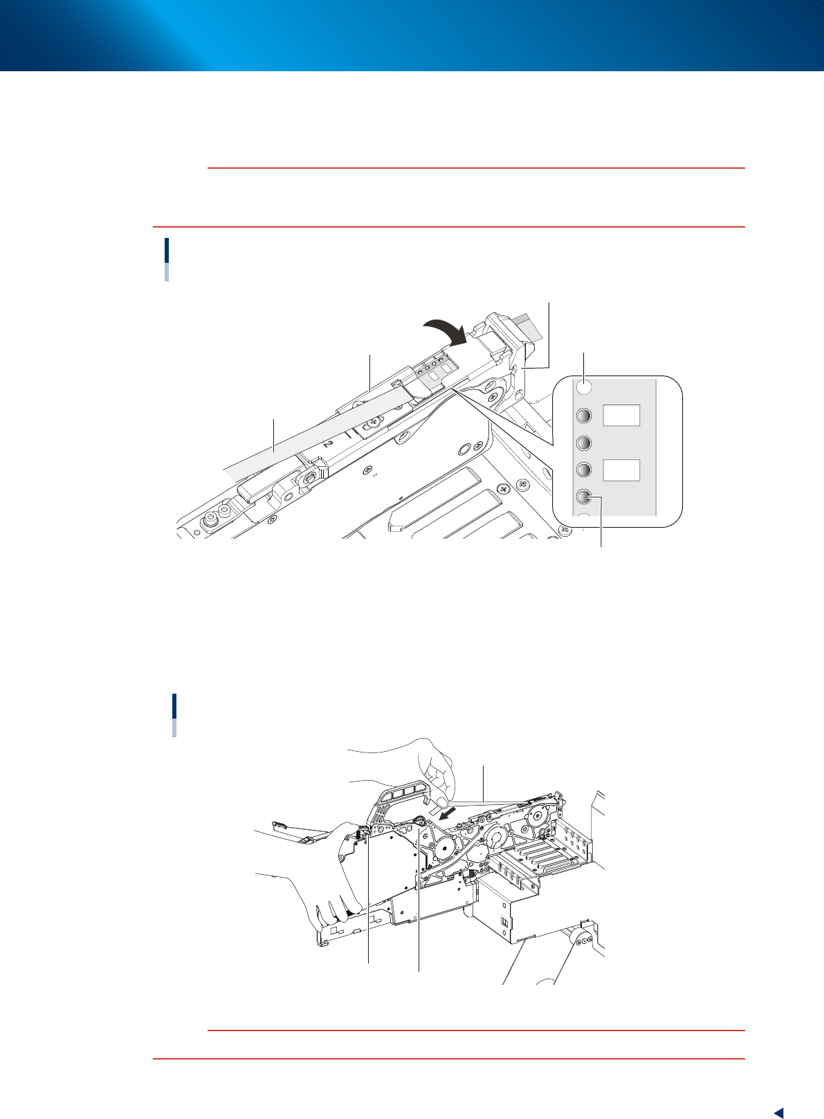
Clamp the tape guide assembly.
While confirming that the sprocket teeth bite into the carrier tape feeding hole, push down to fix the
tape guide assembly with the tape guide front lever.
c
CAUTION
Upon clamping the tape guide assembly, the squeezing of tape guide assembly into the tape guide front lever may wear
the claw of tape guide front lever. Make sure to lift up the tape guide front lever and then engage the claws of tape guide
assembly and tape guide front lever to clamp the tape guide assembly.
Clamping the tape guide assembly
Tape guide front lever
Sprocket teeth
Cover tape
Tape guide assembly
Carrier tape feeding hole
23207-KMX-00
8
Set the cover tape in the take-up roller.
Push the portion of the take-up roller lever shown in the figure to make a clearance below the take-up
roller. Insert a certain amount of the cover tape into this clearance and release the take-up roller
lever to pinch the cover tape.
Setting the cover tape
Cover tape
Take-up roller
Take-up roller lever
23208-KMX-00
c
CAUTION
Check that the cover tape, extended between the take-up roller and the tape guide assembly, is not twisted.