YRM20_Ope_E.pdf - 第33页
1. Machine main unit 1-2 Chapter 1 Unit names and functions ■ Safety cover This cover must be closed during automatic operation. If opened, emergency stop is triggered. The absorbers are installed on both side of safety …
1. Machine main unit
1-1
Chapter 1 Unit names and functions
1. Machine main unit
Here describes names and functions of major parts of the machine main unit (hereinafter referred to as
machine).
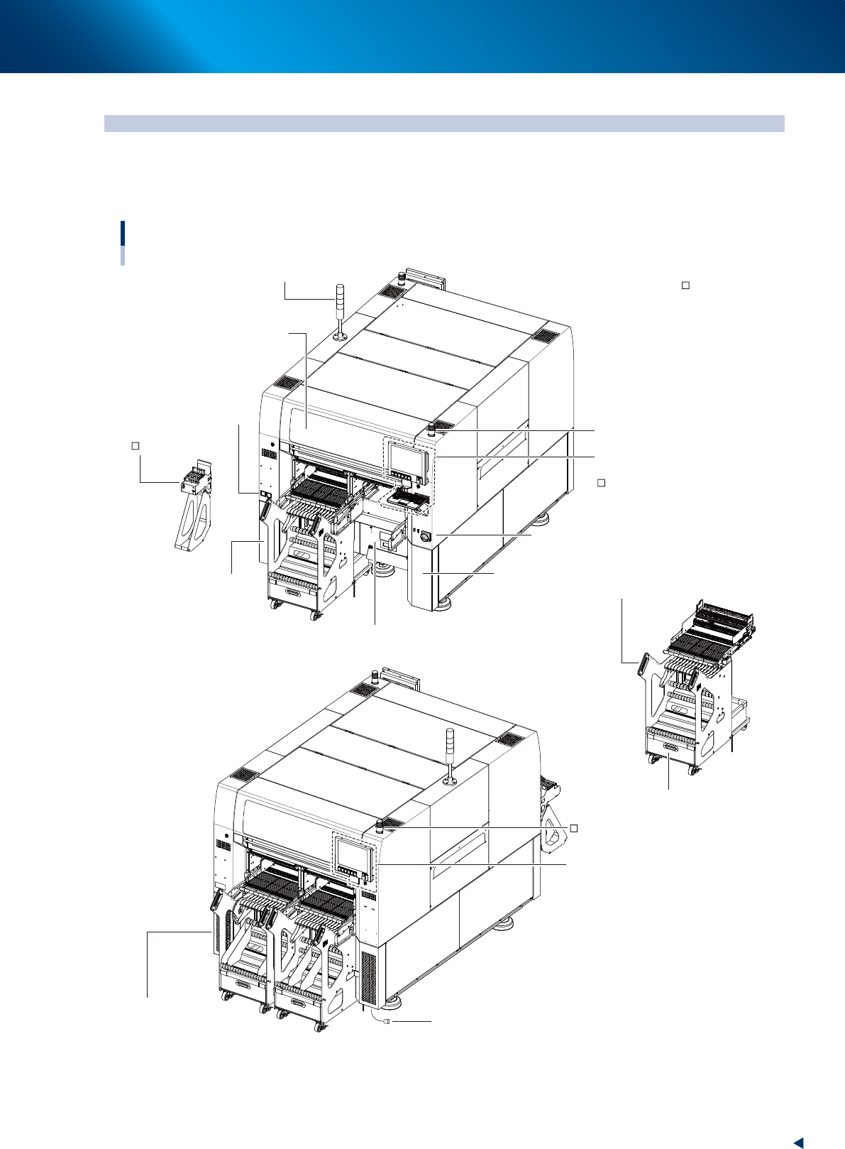
A standard machine has the following configurations after installation is complete.
■ Safety cover
Front
Rear
■ Operation panel and
data input unit
Machine main unit
■ :
Standard units
: Options
Keyboard
Set-up station
Component supply indicator
■ Main switch
■ Power connection terminals
■ Feeder exchange carriage
■ Empty tape dust box
■ Tape cutter
(cover inner side)
■ Pressure gauge
■ Air connection port
■ Operation panel and
data input unit
(rear side)
■ Component supply indicator
■ Signal light
■ Connection between
machines
(panel inner side)
■ Connection between machines
23100-KMX-00
1. Machine main unit
1-2
Chapter 1 Unit names and functions
■
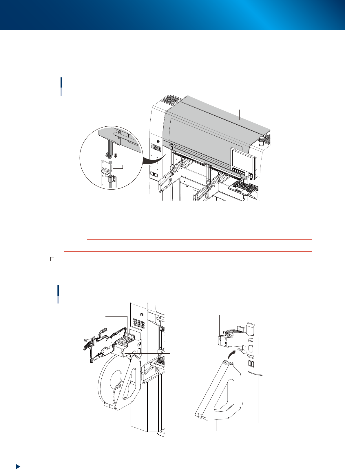
Safety cover
This cover must be closed during automatic operation. If opened, emergency stop is triggered.
The absorbers are installed on both side of safety cover and the cover closes slowly to prevent hands
from pinching. Make sure to confirm the cover closes throughly before starting automatic operation.
Safety cover
Safety cover
Absorber
23140-KMX-00
■
Main switch
Turns on or off the power to the machine. The power is on when turned to the right.
c
CAUTION
Wait about 2 seconds when powering on the machine after powered off it.
Set-up station (option)
This is used for setting component tapes in feeders.
It can be installed at front left/rear right of machine.
Set-up station
Guide rail
Display
(Pitch indication)
Tape reel holder
Power signal connector
23101-KMX-00
1. Machine main unit
1-3
Chapter 1 Unit names and functions
■
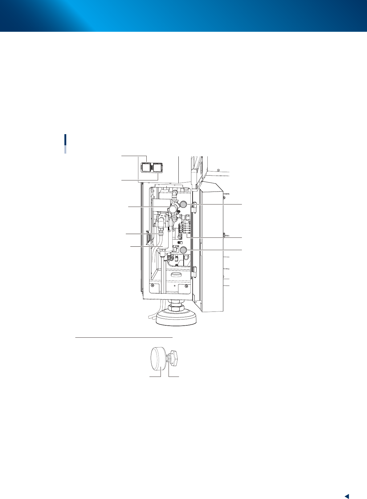
Pressure gauge
The set air pressure display on bottom left as viewed from the front of the main unit (see the figure
below).
Set air pressure : 0.40MPa
Interlock settings : lower limit 0.33MPa, upper limit 0.45MPa
■
Air connection port
The air hose from the air source is connected here. The machine is supplied air by turning supply/
exhaust switch to right. When the switch is turned to left, the air supply to machine is stopped and the
machine's internal residual pressure is released.
Sections for connecting air, pressure adjustment and indicator
Air supply/exhaust switch
Pressure gauge
(Head unit A)
Pressure gauge
(Head unit B)
Supply air connection
Solenoid valve to clamp
the feeder exchange carriage
Air/oil mist filter
Air pressure regulator
(Head unit B)
Air pressure regulator
(Head unit A)
How to lock air pressure regulator handle
Turn clockwise the lock nut at the root of the handle with a wrench (8 mm) and secure it.
Tightening torque: 1 to 1.5 N·m
* After the lock nut has come into contact with the main body, turn it further by 15 degrees as a
guideline.
Handle Lock nut
23103-KMX-00