YRM20_Ope_E.pdf - 第96页
Chapt er 2 Basic op er at ion Contents 1. Before operation 2-1 1. 1 Canceling emergency st op 2-1 1.2 Clearing an error 2-2 1.3 T ypical errors and troubleshooting 2-3 1.4 Swit ching the display language 2-8 2. Operation…
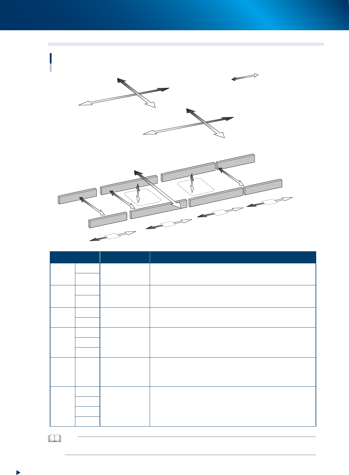
7. Axis configuration
1-64
Chapter 1 Unit names and functions
7.2 Main axis and conveyor axis configuration
W1&W2-axis
YB-axis
YA-axis
XA-axis
XB-axis
W4-axis
U-axis
Main-axis and conveyor-axis configuration
■ Main axes
■ Conveyor axes
Mounting stage 2
Mounting stage 1
Exit conveyor
W3-axis
PU2-axis
PU1-axis
CV2-axis
CV3-axis
CV4-axis
CV1-axis
Plus direction
Minus direction
23139-KMX-00
Axis Specification Function
X-
axis
XA
Motor and boll
screw
Moves the head unit parallel to the board carrying direction of
conveyor.
The rightward viewed from front is plus direction.
XB
Y-
axis
YA
Linear motor
Moves the head unit to right angle of the board carrying direction of
conveyor.
The rearward is plus direction.
YB
PU-
axis
PU1
Motor and timing
belt
Ascends the push-up plate.
The upward is plus direction.
PU2
W-
axis
W1&W2
Motor and timing
belt
Changes the conveyor width.
The direction of conveyor widening is plus direction.
W3
W4
U-
axis
-
Motor and timing
belt
Moves the whole mounting stage 2 to Y direction. The rearward is plus
direction.
It shorten the mounting time by putting close the head unit and the
component mounting position.
CV-
axis
CV1
Motor and timing
belt
Drives conveyor belt to carry the boards.
The direction of carriying the board from right to left is plus direction.
CV2
CV3
CV4
TIP
•The conveyor width changing axis (W2-axis) and W1-axis of the mounting stage 1 are driven together by one motor.
•The front head unit is called "head unit A", and the rear, "head unit B".

Chapter 2 Basic operation
Contents
1. Before operation 2-1
1.1 Canceling emergency stop 2-1
1.2 Clearing an error 2-2
1.3 Typical errors and troubleshooting 2-3
1.4 Switching the display language 2-8
2. Operation screen and buttons 2-10
2.1 Basic configuration of operation screen 2-10
2.2 Setup screen 2-15
2.3 Unit screen 2-17
3. Displaying the production monitors 2-25
3.1 Production 2-25
3.2 Main 2-27
3.3 Vision 2-29
3.4 Alignment 2-32
3.5 Retry 2-33
3.6 Fiducial 2-34
3.7 Badmark 2-35
3.8 Pick Pos. (Pickup position offset) 2-36
3.9 Pick Rate Warning 2-38
3.10 Schedule task 2-42
3.11 Nozzle health check 2-44
3.12 Gap of pick-up position 2-46

4. Preparing component tape 2-47
4.1 Tape feeders 2-47
4.1.1 Setting component tape on the feeder 2-47
4.1.2 Setting feeders on the feeder exchange carriage 2-57
4.1.3 Attaching the feeder exchange carriage on the mounter 2-61
4.1.4 Setting board data of component tape 2-64
4.1.5 Disposing of used cover tape and carrier tape 2-66
4.1.6 Detaching the feeder exchange carriage 2-69
4.1.7 Detaching feeder from the feeder exchange carriage 2-71
4.1.8 Detaching component tape from feeder 2-72
4.2 SS Feeder 2-75
4.2.1 Setting SS feeder on the feeder exchange carriage 2-76
4.2.2 Attaching the feeder exchange carriage on the mounter 2-78
4.2.3 Detaching the feeder exchange carriage from mounter 2-80
4.2.4 Detaching SS feeder from carriage 2-82