YRM20_Ope_E.pdf - 第129页
3. Displaying the production monitors 2-32 Chapter 2 Basic operation 3.4 Alignment T his screen shows a list of the mounting position correction amount follo wing up on component recognition results during the automatic …

3. Displaying the production monitors
2-31
Chapter 2 Basic operation
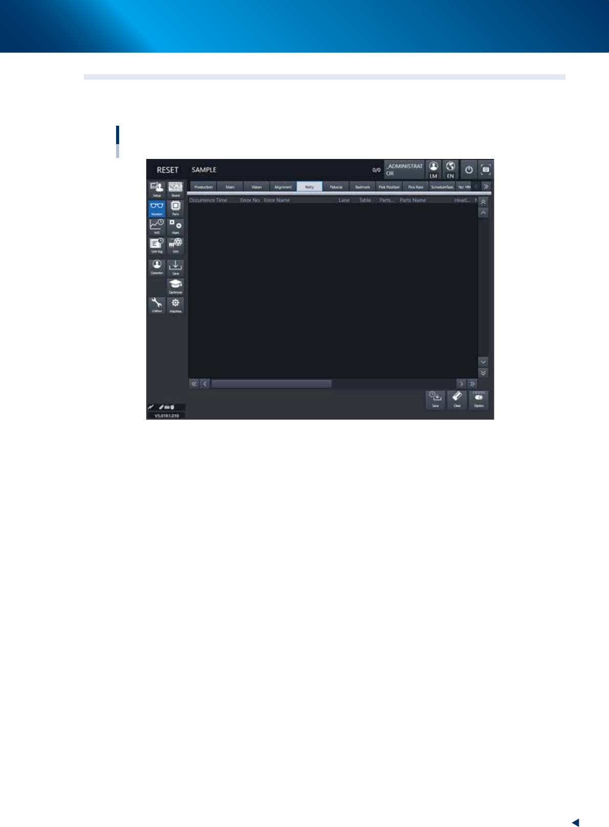
• Error Image
Displays the error image. (Possible only in specific recognition modes.)
• Individual data
Displays the individual data when multiple objects are detected. (Possible only in specific recognition
modes.)
• [Img Check] button
Pressing the [Img check] button calls up the “Vision Check and Save” screen.
The recognized image just before the machine stops due to an error can be checked and saved.
(See "Programming Manual" for more details.)
3. Displaying the production monitors
2-32
Chapter 2 Basic operation
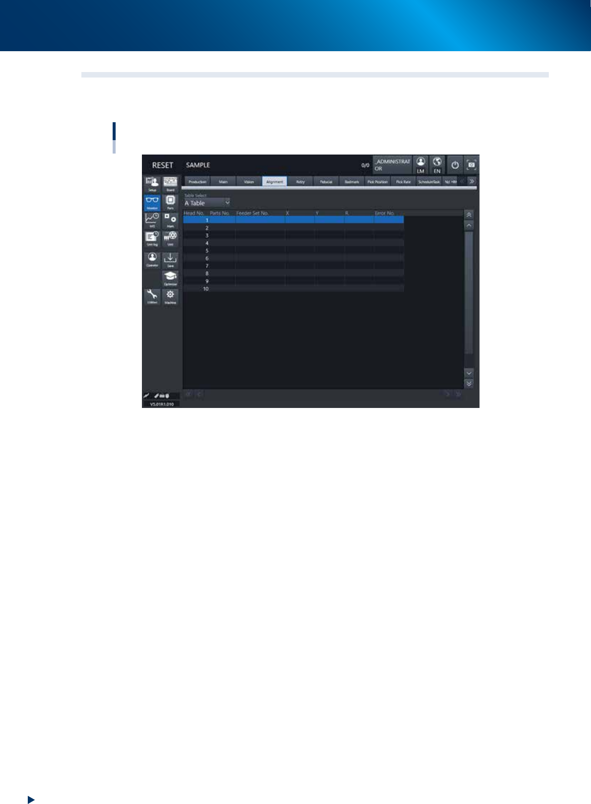
3.4 Alignment
This screen shows a list of the mounting position correction amount following up on component recognition
results during the automatic operation, error numbers and the like.
Monitor: Alignment
24215-KMX-00
• Table Select
Select a head unit.
• Head No.
The head number indicates the component recognition results of one sequence for each head that starts
with the current pickup operation.
Note that the indication reflects the results after the camera finishes recognizing the image.
• Parts No.
Shows the number of the component picked up by the head and recognized with the camera.
• Feeder Set No.
Shows the feeder set number of the component picked up by the head and recognized with the camera.
• X, Y, R
Displays the offset amount of each head calculated from the recognition results obtained during
automatic operation. This offset is the positional deviation from the center of the nozzle.
• Error No.
Shows an error number when the head fails to recognize a component.