YRM20_Ope_E.pdf - 第29页
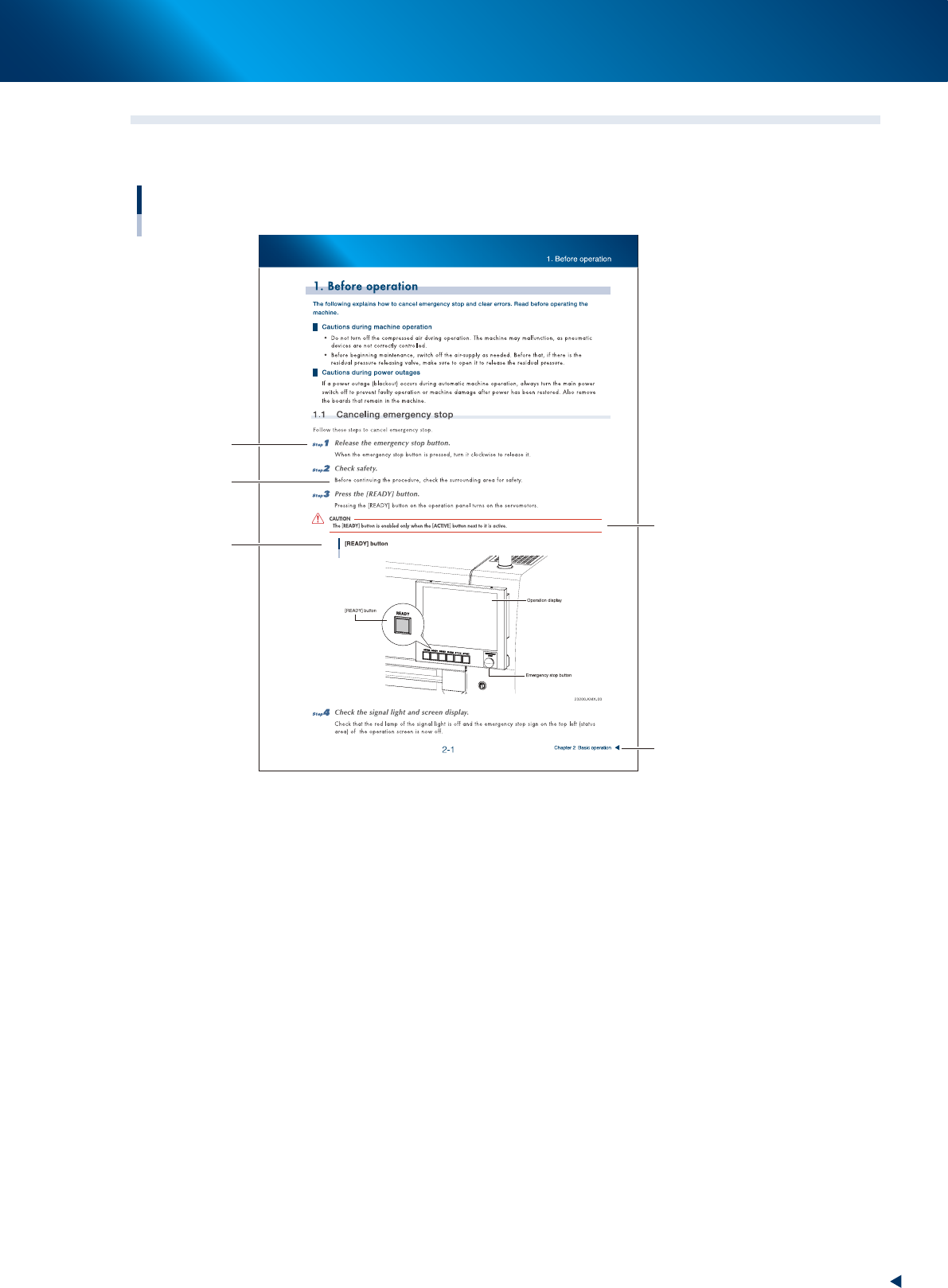
1. Using this manual iii About this manual 1.2 Page layout The description below shows a typical page layout used in this manual. T ypical page layout Step Substep or description of step Figure, picture or table caption …

1. Using this manual
ii
About this manual
1.1 Contents of each chapter
This manual is comprised of the following chapters.
Safety instructions
This section provides safety instructions essential when using the machine.
About this manual
Chapter 1 Part names and functions
Explains major part names and functions of the machine that you should know before attempting
operation.
Chapter 2 Basic operation
• Explains how to use buttons and screen descriptions.
• Explains how to set components up on the tape feeder and set it up on the machine.
• Explains typical errors and their remedial actions.
Chapter 3 Starting up the machine and manufacturing products
Explains a series of procedures from starting up the machine, manufacturing and ending manufacturing.
Appendix
Contains machine specifications.
Index
The index at the end of this manual helps you quickly find where necessary items are explained.
1. Using this manual
iii
About this manual
1.2 Page layout
The description below shows a typical page layout used in this manual.
Typical page layout
Step
Substep or
description of step
Figure, picture
or table caption
Note, Caution
or Warning
Chapter title
23000-KMX-00
■
Step
Describes the procedure for each operation.
■
Substep or description of step
Describes steps in detail.
■
Figure or table caption
This is the title of the figure or table and appears at the upper left.
■
Note, Caution or Warning
These are explained in detail in "Safety instructions".

Chapter 1 Unit names and functions
Contents
1. Machine main unit 1-1
2. Operation panel and data input unit 1-5
2.1 Operation display screen/Operation button 1-6
2.2 Keyboard (option) 1-8
2.3 Other connection ports 1-9
3. Head unit 1-10
3.1 Component pick-and-place head 1-11
3.1.1 RM Head unit 1-11
3.1.2 HM Head unit 1-13
3.2 Nozzle types 1-14
3.3 Nozzle station (option) 1-16
3.3.1 Overview of Nozzle station 1-16
3.3.2 Nozzle holder 1 and 2 1-17
3.3.3 Type A nozzle holder 1-18
3.3.4 Type B nozzle holder 1-19
3.3.5 Attaching/Detaching nozzle holder 1-20
3.4 Blow station 1-22
3.4.1 Shaft-blow function 1-22
3.4.2 Manual nozzle shaft blow procedure 1-23
3.4.3 Automatic nozzle shaft blow procedure 1-28
3.4.4 Shaft blow dump of very small components 1-31
3.5 Vacuum pump ( RM head) 1-32
3.5.1 Vacuum pump (RM head) 1-32
4. Component supply section 1-33
4.1 Machine layout 1-33
4.2 Supplying component tape 1-35
4.2.1 Feeder exchange carriage 1-35
4.2.2 Feeder exchange carriage attaching section of machine 1-38
4.2.3 Attaching/Detaching upper cover 1-41
4.3 One-stop cover (option) 1-45