YRM20_Ope_E.pdf - 第63页
3. Head unit 1-32 Chapter 1 Unit names and functions 3.5 V acuum pump ( RM head) 3.5.1 V acuum pump (RM head) RM head unit generates v acuum for component pick-up b y vacuum pump. T he v acuum pump is installed at the in…
3. Head unit
1-31
Chapter 1 Unit names and functions
3.4.4 Shaft blow dump of very small components
Regarding to disposal of very small components less than 0603 size on this machine, if some components or
dust are recognized at checking after disposing operation, the air-blow station continues the shaft blow dump.
The target components for the shaft blow dump are determined by the following three settings.
1. The machine is equipped with the air-blow station.
2. The function of the shaft blow dump is set "Use" in "Machine Data"-"Mechanical"-"Position" and
"Dump Size" and "Blow Timer" are appropriately set.
3. The size of the component to be disposed of is less than the setting value in 2.
Additionally, to check the disposal, if "B: Bring Back Check" in [Parts]-[Side View] is set with "Use", the side
view camera is used for judgement. If it is set with "Not Use", the vacuum pressure check is used for
judgement.
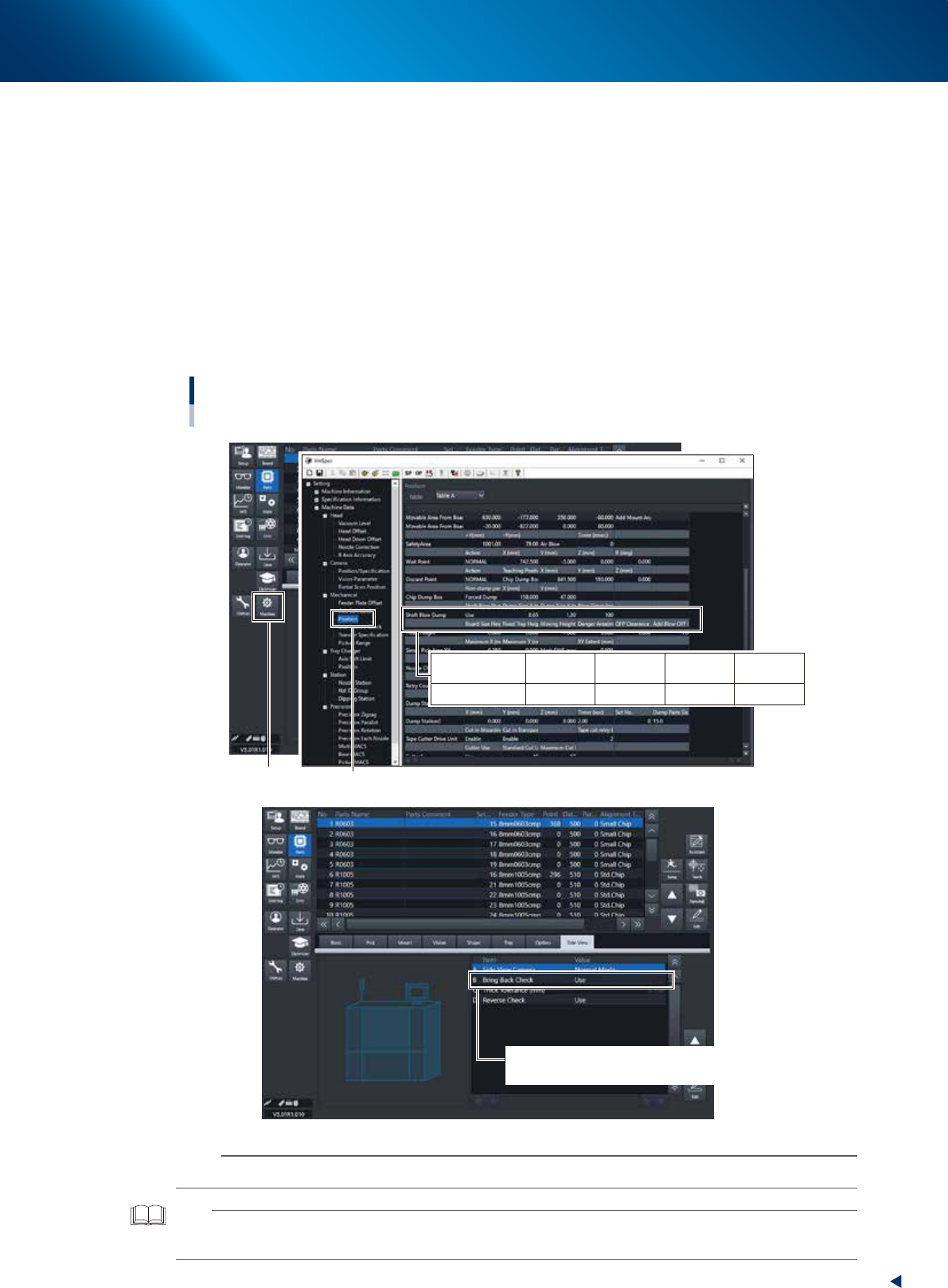
Setting the Shaft Blow Dump
Board data : [Parts] - [Side View]
Setting : “Machine Data” - ”Mechanical” - “Position”
[Machine] button
“Mechanical” - ”Position”
B Bring Back Check/Use : Judged by the side view camera
Bring Back Check/ Not Use : Judged by the vacuum pressure
Shaft Blow Dump
Dump Size
X (mm)
0.65
Dump Size
Y (mm)
1.30
Shaft Blow
Dump
Use
Blow Timer
(msec)
100
24108-KMX-00
n
NOTE
The shaft blow dump doesn't work if "Shaft Blow Dump" is set with "Not Use", "Dump size" is "0" or "Blow timer" is "0".
TIP
The setting in the figure above is the recommended setting that the shaft blow is only applicable for small components of
size 1005.
3. Head unit
1-32
Chapter 1 Unit names and functions
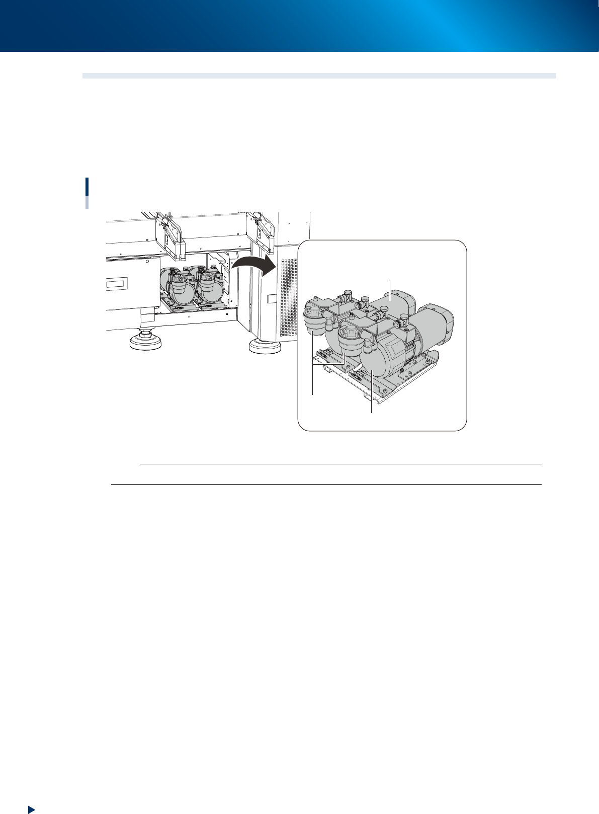
3.5 Vacuum pump ( RM head)
3.5.1 Vacuum pump (RM head)
RM head unit generates vacuum for component pick-up by vacuum pump.
The vacuum pump is installed at the inside of machine rear panel.
The vacuum pump located at rear left of machine, viewed from front, works for front head unit, and the
other, for rear head unit (the figure below is viewed from machine rear).
Vacuum pump (RM head unit)
Vacuum pump
For rear RM head unit
For front RM head unit
Filter
23120-KMX-00
n
NOTE
HM head unit generates vacuum for component pick-up by ejector of head unit.
4. Component supply section
1-33
Chapter 1 Unit names and functions
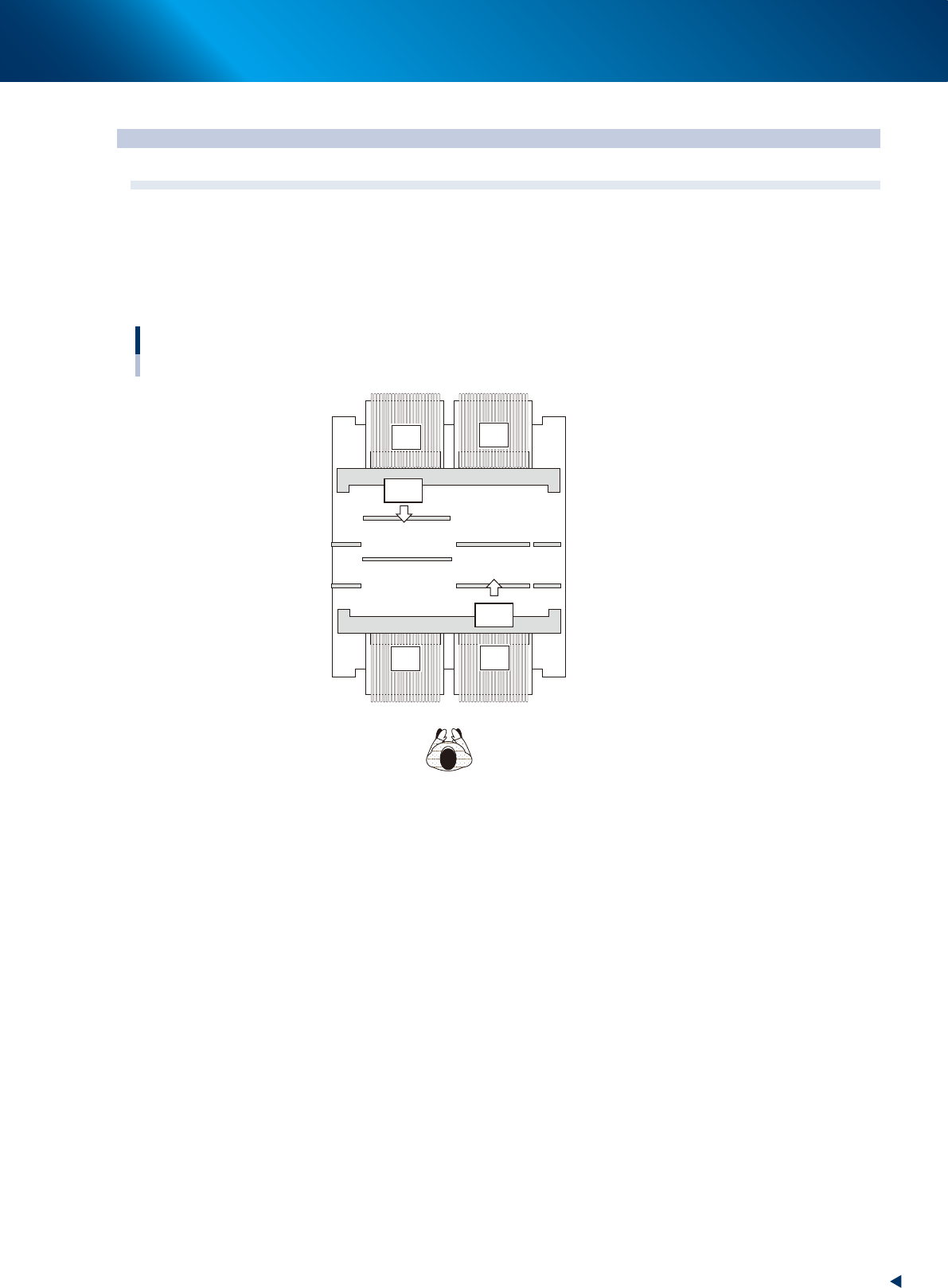
4. Component supply section
4.1 Machine layout
YRM20 has 4 carriage set positions and can be attached the feeder exchange carriage up to 4 units. Also,
each one of carriages can be attached the feeders up to 32 pieces.
The carriage set positions are called F1, F2, R1, and R2, as shown in the figure below.
The feeder set position number of carriage attached to F1 are 1 to 32, of set position F2, 33 to 64, of R1,
101 to 132, of R2, 133 to 164.
Machine layout
32-reel feeder exchange carriage x 4 units
1 32 64
164 132 101
33
133
R1
R2
F1
F2
23121-KMX-00