YRM20_Ope_E.pdf - 第151页
4. Preparing component tape 2-54 Chapter 2 Basic o pera tion ► Button operations and corresponding feed pitches Feeder type Setting Pitch [FEED], [BACK] Pressed 1 Time [FUNC+FEED] [FUNC+BACK] Pressed 1 Time ZS Feeder 4mm…
4. Preparing component tape
2-53
Chapter 2 Basic operation
0
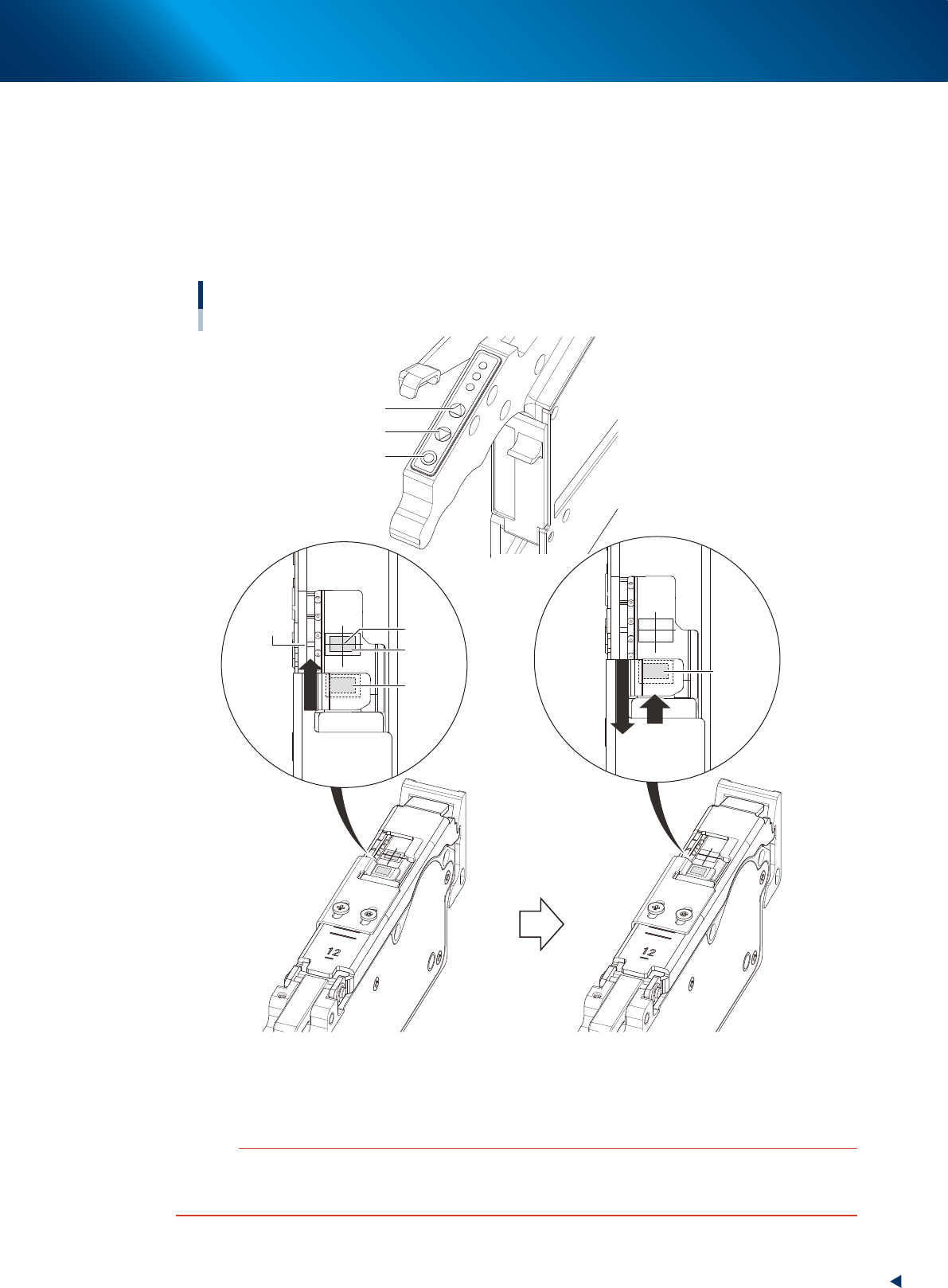
Align the first component with the standby position.
If pressing the [FEED] button and the [BACK] button on the feeder, the tape can be transferred or
returned with the pitch setting corresponding to the feeder type.
1. Press the [FEED] button and transfer the tape temporary to locate the first component on the
pickup position (spot: white mark or notch).
2. After pressing the component pitch and the [BACK] button once to return the component, press
the [FEED] button once and align the first component with the standby position.
Adjusting component position
[FUNC] button
[BACK] button
[FEED] button
Pickup
position
Marking
First
component
Standby
position
First
component
(Standby
position)
Press the [FEED] button to feed the
component to the pickup position.
Press the component pitch and the [BACK] button
once to return the component. Then press the [FEED]
button once and align the first component with the
standby position.
23210-KMX-00
c
CAUTION
Make sure to align the component with the standby position by the [FEED] button. Press the [BACK] button twice or more to
return the component. Then press the [FEED] button to align the component with the standby position. If aligning the
standby position by the [BACK] button, the pickup position offset of the fist component may occur.
4. Preparing component tape
2-54
Chapter 2 Basic operation
►
Button operations and corresponding feed pitches
Feeder type Setting Pitch
[FEED], [BACK]
Pressed 1 Time
[FUNC+FEED]
[FUNC+BACK]
Pressed 1 Time
ZS Feeder 4mm All pitches 1mm 1mm
ZS Feeder 8mm
0 2mm
1mm1 1mm
2 and higher 2mm
ZS Feeder 12/16mm, 24mm,
32mm, 44mm, 56mm、72mm,
88mm, 104mm
0
2mm
2mm
2 and higher Setting pitch
TIP
• For handling the feeder of 12 mm or wider, set the components pitch on the power station. Then, press the [FUNC] and
[FEED] buttons or the [FUNC] and [BACK] buttons simultaneously. The feeder feeds the tape by the set pitch. See
Chapter 2, "5. Setting tape feed pitch" in "ZS/ZSR FEEDER User's Manual" for the setting.
• Continuous feed is possible by pressing and holding the "FEED / BACK" button.
• Continuous feed is not possible by pressing and holding the "FUNC + FEED" and "FUNC + BACK" buttons.
• See the “SS Feeder User’s Manual” for setting the feed pitch of SS feeder.
4. Preparing component tape
2-55
Chapter 2 Basic operation
q
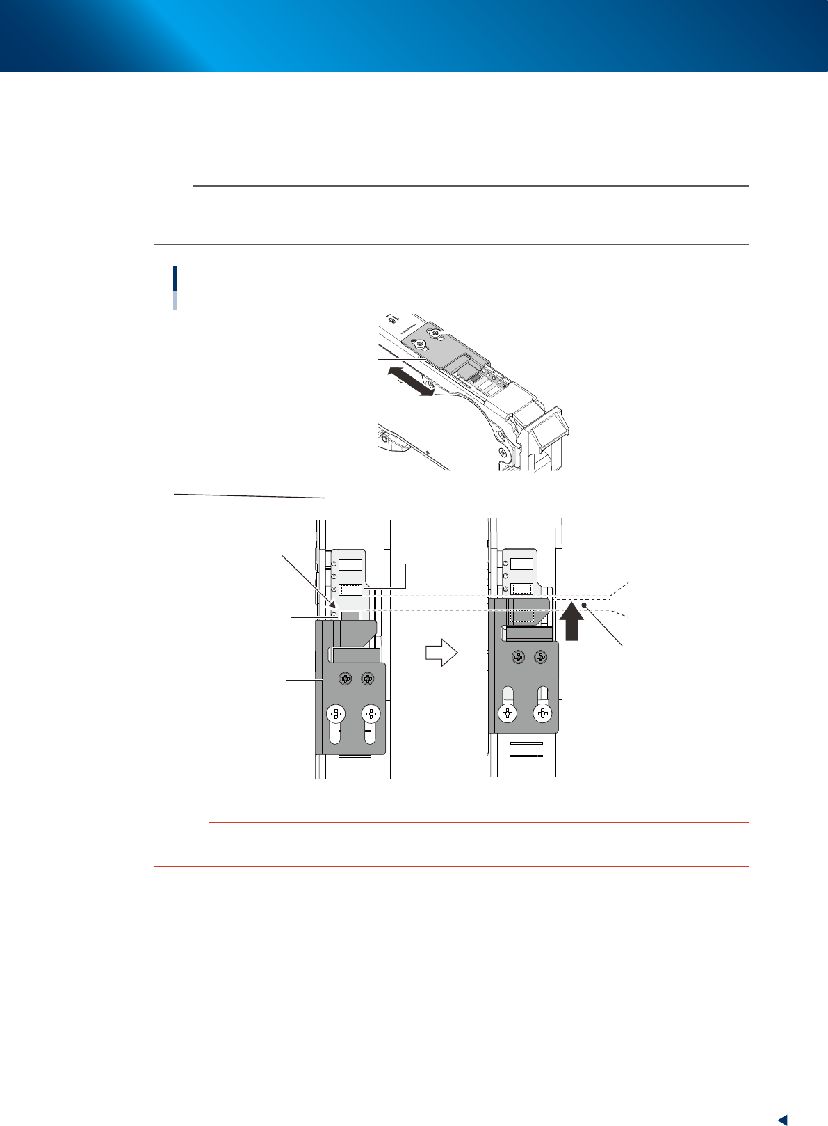
Check and adjust the tape support plate position.
If the feeder type is 12 mm or wider, it is required to adjust the tape support plate according to the
components shape. Adjust the tape support plate position by loosening the 2 adjustment screws with
Phillips screwdriver. Locate the tape support plate between A and B illustrated below (closer to A).
n
NOTE
The cover tape is required to be adjusted upon changing the tape support plate position. When the cover tape shortens,
push the take-up roller lever, as the same procedure of Step 8, and pull out cover tape from take-up roller. When some
slack is on cover tape, remove it.
Adjusting tape support plate position
Not supported appropriately
Pickup pocket
(Component pickup
position)
Standby position pocket
(Component standby position)
A. Front side of
pickup pocket
B. Rear side of
stanby position pocket
Place the leading edge of
tape support plate at rear side
of the center of A and B
Adjusting tape support plate
Slide the tape support plate
Tape support plate
Tape support plate
Adjustment screw
23211-KMX-00
c
CAUTION
If the tape support plate is not adjusted, the components may pop out after removing the cover tape, or its pickup position
may get unstable.