YRM20_Ope_E.pdf - 第52页
3. Head unit 1-21 Chapter 1 Unit names and functions Attaching/Detaching nozzle holder Nozzle holder • Detaching nozzle holder • Attaching nozzle holder Click! Nozzle holder detection sensor Nozzle holder detaching lever…
3. Head unit
1-20
Chapter 1 Unit names and functions
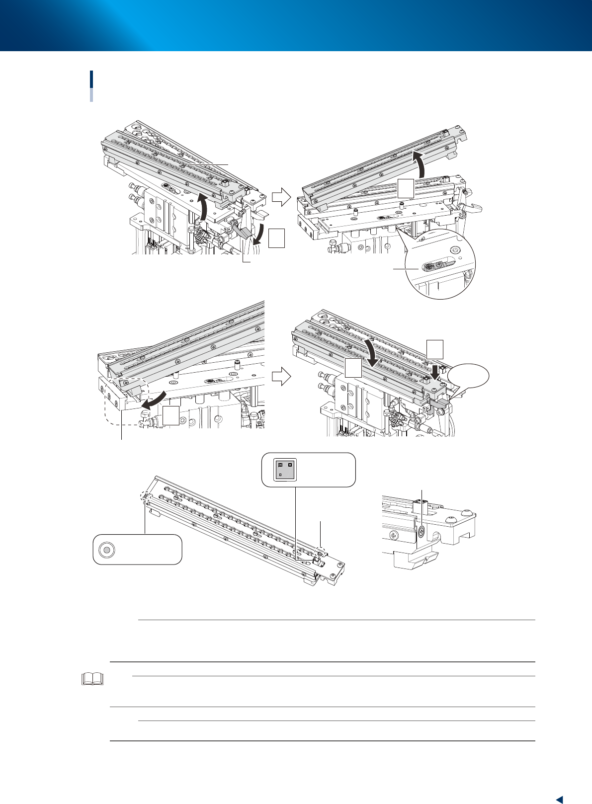
3.3.5 Attaching/Detaching nozzle holder
█
Detaching nozzle holder
1. Push down the nozzle holder detaching lever.
2. Lift up the whole nozzle holder and detach it.
█
Attaching nozzle holder
1. Insert the nozzle holder like hooking the mounting block unit of nozzle station base unit.
2. Push down the lever side of nozzle holder while making the mounting block side as a supporting
point.
3. Press the nozzle holder downward. It clicks upon being locked.
n
NOTE
The nozzle holder shutter is equipped with magnet and it is closed after detaching the nozzle holder.
The nozzle can be detached while shifting the shutter by hand.
Moreover, do not make upside down the nozzle holder with opening the shutter as the nozzles may drop off.
3. Head unit
1-21
Chapter 1 Unit names and functions
Attaching/Detaching nozzle holder
Nozzle holder
• Detaching nozzle holder
• Attaching nozzle holder
Click!
Nozzle holder
detection sensor
Nozzle holder
detaching lever
ANC MACS
ANC MACS
QR code
Mounting block
1
2
4
5
3
Magnet
23117-KMX-00
n
NOTE
The position of nozzle holder is calibrated by scanning a positioning mark (ANC MACS) with fiducial camera.
Moreover, a nozzle holder detection sensor is equipped at mounting position of nozzle holder and the automatic operation
without nozzle holder is prevented by interlock.
TIP
MACS is an abbreviation of "Multiple Accuracy Compensation system" and used to mean the position correction system
for YAMAHA mounter or the positioning mark.
n
NOTE
Be careful not to scratch or dirt the QR code label and ANC MACS, or it may occur a recognition error.
3. Head unit
1-22
Chapter 1 Unit names and functions
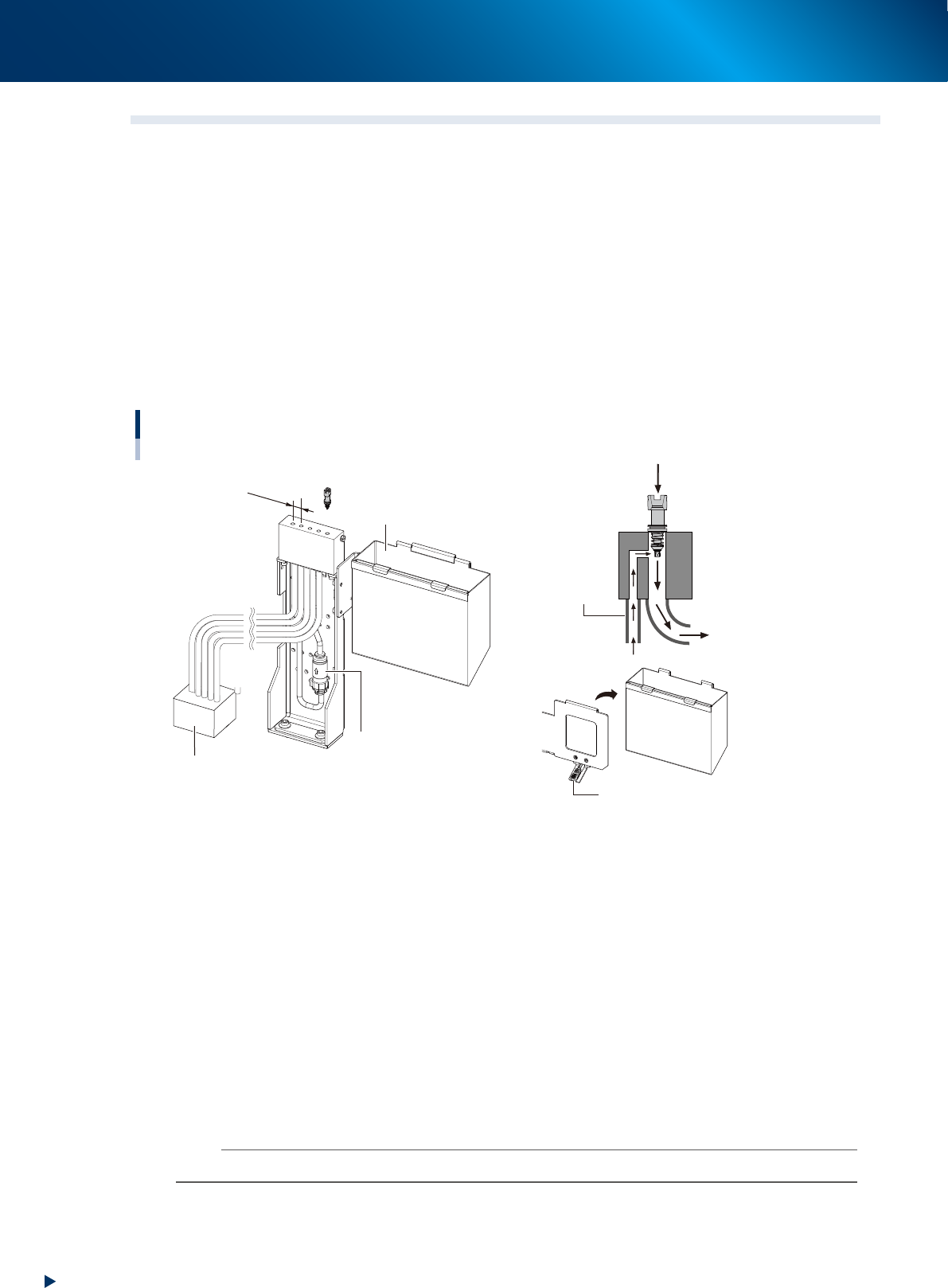
3.4 Blow station
3.4.1 Shaft-blow function
The air-blow station provides a high-pressure air blowing cleaning function to blow foreign matter from the
nozzles, inside the shafts and nozzl tip (This motion is called Nozzle Shaft blow).
The air-blow stations are installed at front and rear side of machine.
Five holes shown in the figure below are used to blow the heads separated in groups. See"3.4.2 Manual
nozzle shaft blow procedure" for practical method.
Here, components are normally disposed into the dump box. But regarding to the disposal of very small
components as such 1005 size or smaller, if some components or dust are recognized at checking after
disposal operation (by negative pressure check or side view recognition), the air-blow station continues shaft
blow dump to dispose very small components.
See the section"3.4.4 Shaft blow dump of very small components" for practical method.
Air-blow station and dump box
Dump box
confirmation sensor
Dump box
Exhaust box
Shaft blow
Side blow
Air-blow station filter
12mm
23118-KMX-00
■
Side blow
Cleans the nozzle tip by air-blow from side when the nozzle shaft-blow is performed.
■
Air-blow station filter
The filter for the side-blow line in the air-blow station.
■
Dump box
A box to dispose the discarded components.
■
Dump box confirmation sensor
Checks the dump box presence and floating status.
■
Exhaust box
Stores dust and vert small chips disposed by the nozzle shaft-blow.
n
NOTE
The automatic operation cannot be started without the dump box in its position.