YRM20_Ope_E.pdf - 第128页
3. Displaying the production monitors 2-31 Chapter 2 Basic operation • Error Image Displays the error image. (Possible only in specific recognition modes.) • Individual data Displays the individual data when multiple obj…

3. Displaying the production monitors
2-30
Chapter 2 Basic operation
• Parts Monitor Mode
This specifies the mode for displaying the components on the monitor during vision recognition.
Depending on the selected item, the recognition results and detection range window will appear on the
image. This monitor mode can also be changed during operation.
• None
Displays the image taken by the camera. The recognition result values are not displayed.
• Vision Result
Displays information such as the recognition results X, Y and R direction position (pixels) and number of detection
leads. Note that the displayed items will differ according to the component recognition type.
• Detection Range
Draws a window for the component detection range. If the component does not fit within the
detection range, it will not be recognized correctly. In this case, check the pickup state or correct the
component data.
• Datum Pos.
Displays a cross cursor indicating the position used as a reference for detecting the lead or
component edge.
• Find Line
Displays the line used for component detection, on a chip component or on the component leads. If
the detection line position is incorrect, adjust the Vision parameters.
• Edge Pos
Displays a cross cursor at the lead or component edge position.
• Last Pos.
Displays a cross cursor at the center of the component.
• Binary Image
The component is displayed as a binary image.
• Mark monitor mode
This specifies the monitor display mode during mark recognition. The recognition results and binary
image will appear on the image according to the selected item. This monitor mode can be changed
during operation.
• None
Displays an image taken by the camera. The recognition result values are not displayed.
• Result
Displays the center position coordinates (pixels) of the detected mark.
• Binary Image
Displays the image taken by the camera as a binary image.
• Grey Image
Displays an image that was processed after being captured by the camera. The recognition result
values are not displayed.
• Search Result
Draws a line to indicate the boundary between the recognized mark and the background.
• Datum Circle
Draws a mark of the specified diameter from the center of the detected mark. (Possible only in
specific recognition modes.)
• Tangent Circle
Draws an inscribed circle and circumscribed circle from the center of the detected mark. (Possible
only in specific recognition modes.)

3. Displaying the production monitors
2-31
Chapter 2 Basic operation
• Error Image
Displays the error image. (Possible only in specific recognition modes.)
• Individual data
Displays the individual data when multiple objects are detected. (Possible only in specific recognition
modes.)
• [Img Check] button
Pressing the [Img check] button calls up the “Vision Check and Save” screen.
The recognized image just before the machine stops due to an error can be checked and saved.
(See "Programming Manual" for more details.)
3. Displaying the production monitors
2-32
Chapter 2 Basic operation
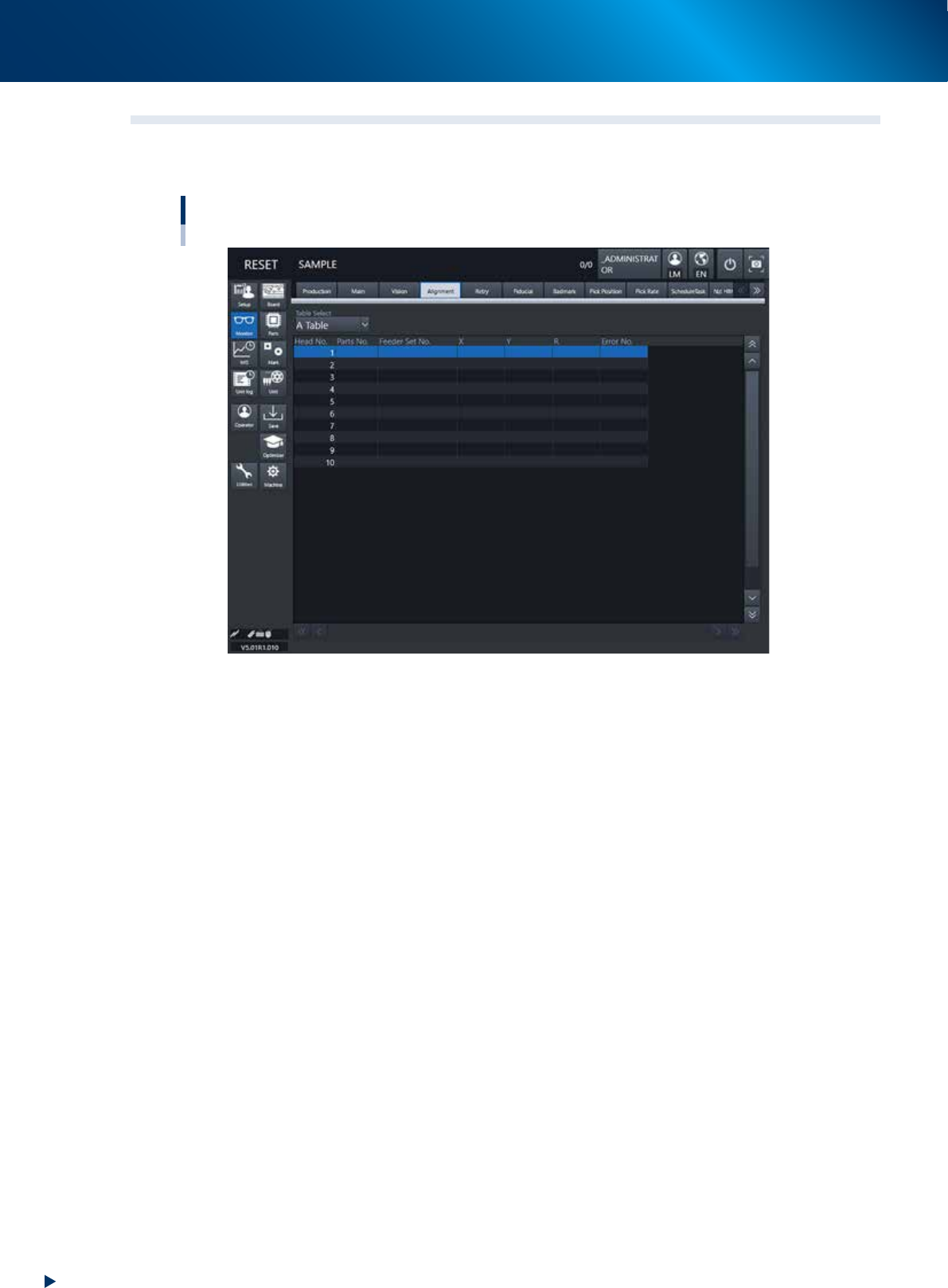
3.4 Alignment
This screen shows a list of the mounting position correction amount following up on component recognition
results during the automatic operation, error numbers and the like.
Monitor: Alignment
24215-KMX-00
• Table Select
Select a head unit.
• Head No.
The head number indicates the component recognition results of one sequence for each head that starts
with the current pickup operation.
Note that the indication reflects the results after the camera finishes recognizing the image.
• Parts No.
Shows the number of the component picked up by the head and recognized with the camera.
• Feeder Set No.
Shows the feeder set number of the component picked up by the head and recognized with the camera.
• X, Y, R
Displays the offset amount of each head calculated from the recognition results obtained during
automatic operation. This offset is the positional deviation from the center of the nozzle.
• Error No.
Shows an error number when the head fails to recognize a component.