YRM20_Ope_E.pdf - 第37页
2. Operation panel and data input unit 1-6 Chapter 1 Unit names and functions 2.1 Operation display scr een/Operation button Machine oper ation and data editing procedures are performed at the operation displa y screen (…
2. Operation panel and data input unit
1-5
Chapter 1 Unit names and functions
2. Operation panel and data input unit
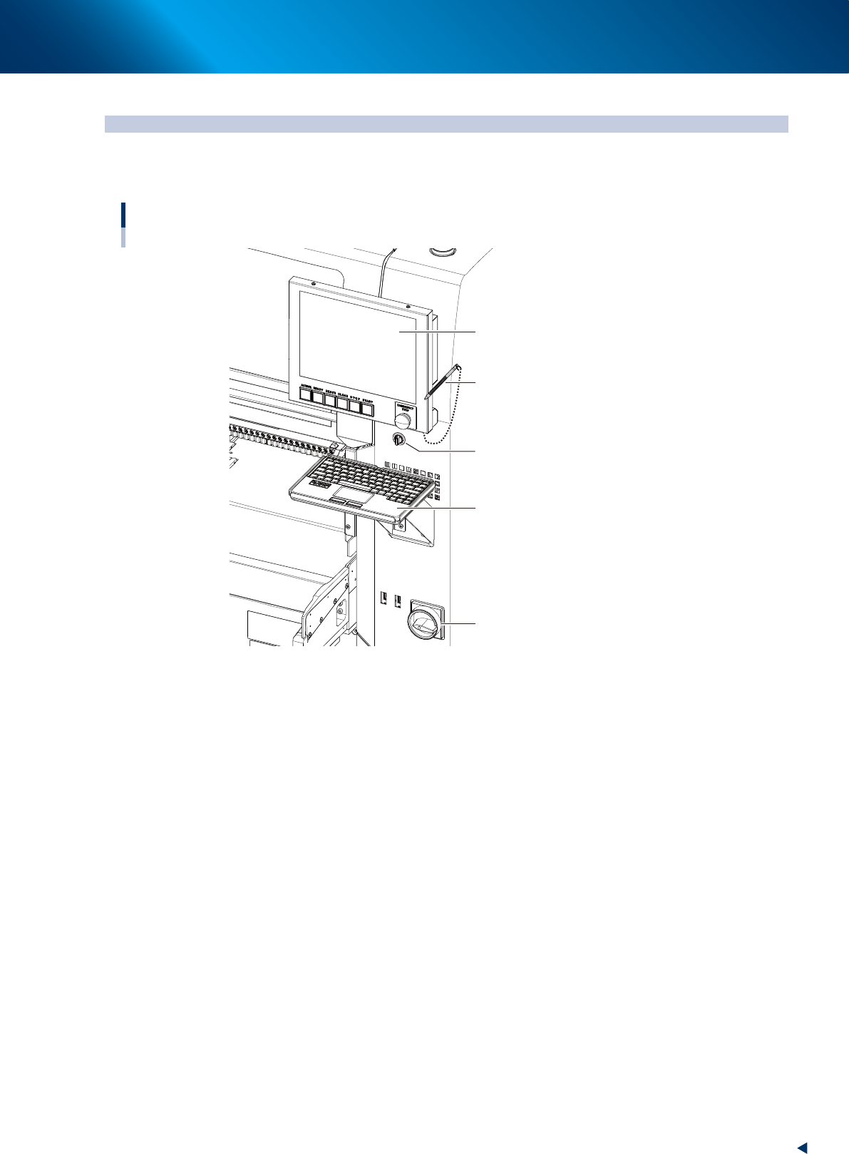
Operation panels and operation display screens for data inputs are provided at both the front and rear
of the machine. The functions of these units are explained below.
Operation display screen
Key board
Main switch
Touch pen
Operation display screen
(Touch panel)
Feeder exchage carriage
clamp switch
23104-KMX-00
2. Operation panel and data input unit
1-6
Chapter 1 Unit names and functions
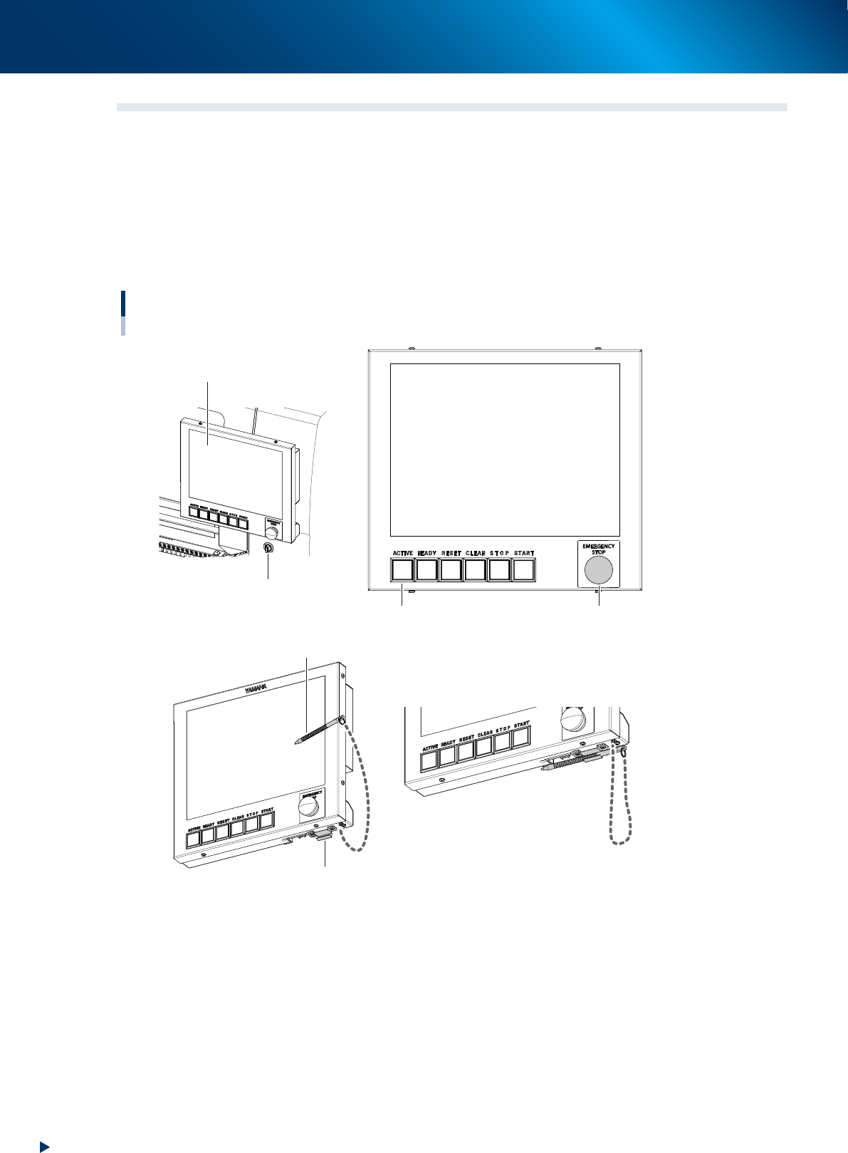
2.1 Operation display screen/Operation button
Machine operation and data editing procedures are performed at the operation display screen (touch-panel
specifications). A touch pen is used to select the onscreen buttons and parameter items. Be sure to return
the touch pen to its holder when it is not in use.
Operation button and emergency stop button are integrated to operation display screen.
These buttons play the role to operate machine, emergency stop, error clear or so, which are performed
directly by operators.
Buttons light up when machine is turned on. Moreover, lighting color of each buttons are the same as set for
signal lights.
Operation display screen / operation button
Touch pen
Touch pen holder
Operation display screen
Feeder exchage carriage
clamp switch
Emergency stop button
Operation buttons
23105-KMX-00
2. Operation panel and data input unit
1-7
Chapter 1 Unit names and functions
►
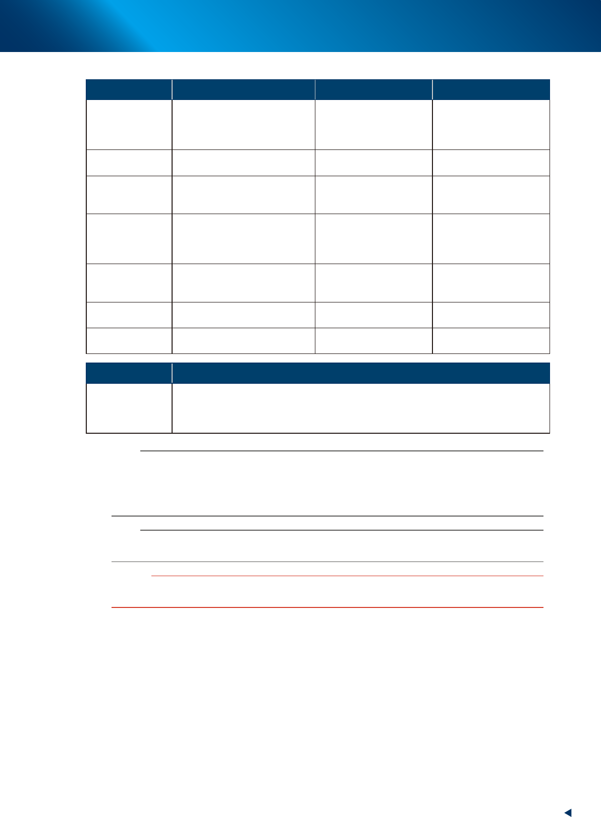
Functions and status of operation button/ emergency stop button
Button name Application OFF ON
ACTIVE
Enable other operation buttons and
touch panel on the side in use.
(The front and rear [ACTIVE] keys
cannot be enabled simultaneously.)
• After machine has started.
• The other side has access
rights to operate machine.
• Has access rights to
operate machine.
READY
Release emergency stop and turn
the servo on.
• SERVO OFF
(Motor power OFF)
• SERVO ON
(Motor power ON)
RESET
Stop automatic operation and
return to standby for board
production.
• Machine is in normal
operation or stopped.
• Machine has been reset.
START (green)
Perform component placement
according to board data.
• Machine is stopped.
• Machine is in normal
operation.
[Flash]
Pause or step operation
STOP (Red/White)
Interrupt automatic operation.
(Press START to resume
operation.)
• Machine is in normal
operation.
• Error occurred.
ERROR CLEAR
(Yellow/Blue)
Stop buzzer sound and clear error
screen.
• Machine is in normal
operation.
• Error occurred.
EMERGENCY
STOP
Trigger emergency stop. Turn to
the right to release it.
Switch Name Application
Feeder exchage
carriage clamp
switch
Clamps and fixes the feeder exchange carriage. This switch should be ON by turning to left
upon setting the carriage (clamp) in position, and OFF by turning to right when detaching it.
The LED of switch lights during the feeder exchange carriage is clamped, and flashes during
clamping or unclamping.
n
NOTE
The [ACTIVE] button is provided on both front and rear (option) panels, but cannot be turned on simultaneously.
This means that the [READY], [START], [ERROR CLEAR] and [RESET] buttons are enabled only when the [ACTIVE] key on
the same panel is turned on.
Moreover, the [STOP] button and emergency stop button can be used when the [ACTIVE] button is either on or off.
The keyboard (option) is enabled only when the [ACTIVE] key on the front panel is on.
n
NOTE
The clamping of feeder exchange carriage is performed only when the machine safety cover is closed.
Moreover, the unclamping the feeder exchange carriage is performed only when the machine is under emergency stop.
c
CAUTION
Remove the feeder exchange carriage after the flashing of the clamp switch has stopped. If the feeder exchange carriage
is removed forcibly while the switch is flashing, this may cause malfunction.