YRM20_Ope_E.pdf - 第92页
6. Recognition unit 1-61 Chapter 1 Unit names and functions 6.3 Multi-view cameras Recognition unit Multi-view camera Multi-view camera 23136-KMX-00 ■ Multi-view cameras The multi-camera recognizes components when the co…

6. Recognition unit
1-60
Chapter 1 Unit names and functions
6.2 Side-view function (Scan camera / Side-view camera)
The functions below can be used by Side-view camera and Scan camera to recognize components and
nozzles horizontally.
█
Pickup error detection function
• Simple mode
Detects component pickup errors, thus preventing missed mountings.
Operation can continue without interruption even when nozzles are changed due to nozzle washing,
etc.
• Detailed mode
Detects component pickup errors, thus preventing missed mountings.
Vertical, horizontal, slanting, etc., pickup error judgments are made based on the user-specified
component thickness tolerance.
• Soiled nozzle detection function
If a component is recognized as "present" at component recognition, but as "absent" by the side-
view function, this is judged a "soiled nozzle" condition, and a warning message displays.
This enables the user to better identify the best time to wash a nozzle.
█
Component discard operation skip function
A discard operation skip occurs if the side-view function makes a "component absent" judgment.
This reduces wasted operation when a component has not been picked up, resulting in a lower tact.
█
Component return detection function
Detects a component which is still on the nozzle tip after it should have been mounted or discarded.
█
Upside down check function
Checks (at recognition processing) for components which have been picked up in an upside down
posture. This function also checks to see if the picked-up component size can be contained within
side-view camera's field of view.
An error message displays if the component is recognized as being upside down, or if its size cannot
be contained within side-view camera's field of view.
This function does not apply to components which have upper-half leads or for components which have
no side-face leads.
n
NOTE
For details regarding the side-view function's parameters, refer to the Programming Manual.
6. Recognition unit
1-61
Chapter 1 Unit names and functions
6.3 Multi-view cameras
Recognition unit
Multi-view camera
Multi-view camera
23136-KMX-00
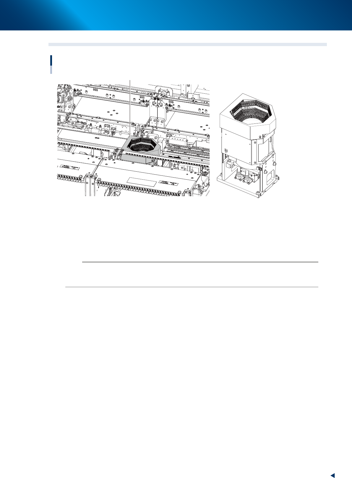
■
Multi-view cameras
The multi-camera recognizes components when the components are mounted with RM head unit or when
the components, which are too big for a scan camera of HM head unit to recognize.
This is installed on either or both of front and rear depending on the head unit selection or its
specification.
n
NOTE
The maximum sizes of components that scan camera equipped to HM head unit can recognize are as below. When the
components size is bigger than this, a multi-view camera is required to recognize the components.
12 mm square, 6.5 mm heigh
7. Axis configuration
1-62
Chapter 1 Unit names and functions
7. Axis configuration
This section describes the axis configuration and the axis movement direction on this machine.
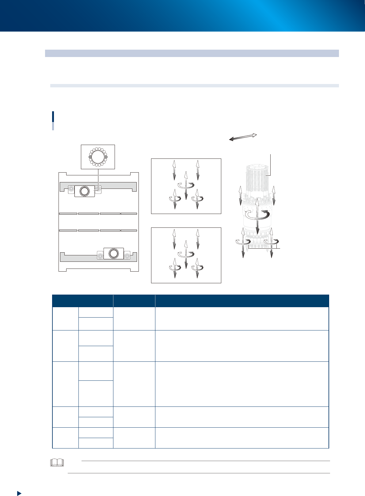
7.1 Head unit axis configuration
7.1.1 RM head unit
1
1
110
2
18
Head axes configuration of RM head unit
Example as viewed from the machine front
Plus direction
Minus direction
R-axis
Z1-axis
Z2-axis
V1-axis
V2-axis
N-axis
HZ-axis
Front side / Head unit A
Rear side / Head unit B
Rotary
ZA2-axis
RA-axis
ZA1-axis
RA-axis
HZA-axis
NA-axis
VA2-axis
VA1-axis
ZB1-axis
RB-axis
ZB2-axis
RB-axis
HZB-axis
NB-axis
VB1-axis
VB2-axis
Head unit A
Machine front
Head unit B
23137-KMX-00
Axis Specification Function
Z-axis
ZA1, ZA2
Linear motor
Are located at both sides of RM head unit. The components are
picked-up/mounted by ascending/descending the one of 18 nozzle
shafts installed in rotary. Z1-axis is also called rod 1, and Z2, rod 2.
ZB1, ZB2
V-axis
VA1, VA2
Linear motor
Are located at both sides of RM head unit.
The stroke of V-axis is narrower than that of Z-axis. V-axis performs
vacuum/air supply switching for nozzle shaft by ascending/descending
the mechanical valve (spool) of rotary.
VB1, VB2
HZ-axis
HZA
Linear motor
Moves the whole RM head unit up-and-down.
It supports the Z-axis motion upon component picking-up/mounting to
shorten mounting time. Also, the RM head unit ascends upon picking-
up a thick component. Moreover, it ascends to fit to component size,
upon recognizing components, to adjust multi-view camera focus.
Downward is plus direction.
HZB
R-axis
RA-
axis
Motor & gear
Rotates all 18 nozzle shafts inside the rotary at the same time.
The counterclockwise, viewed from above, is plus direction.
RB-
axis
N-axis
NA-
axis
Motor & gear
Rotates whole rotary.
The clockwise direction, viewed from above, is plus direction.
NB-
axis
TIP
The front head unit is called "head unit A", and the rear, "head unit B".