YRM20_Ope_E.pdf - 第94页
7. Axis configuration 1-63 Chapter 1 Unit names and functions 7.1.2 HM head unit 10 1 1 10 Head axes configuration of HM head unit Example as viewed from the machine front Plus direction Minus direction RA1-axis RB1-axis …
7. Axis configuration
1-62
Chapter 1 Unit names and functions
7. Axis configuration
This section describes the axis configuration and the axis movement direction on this machine.
7.1 Head unit axis configuration
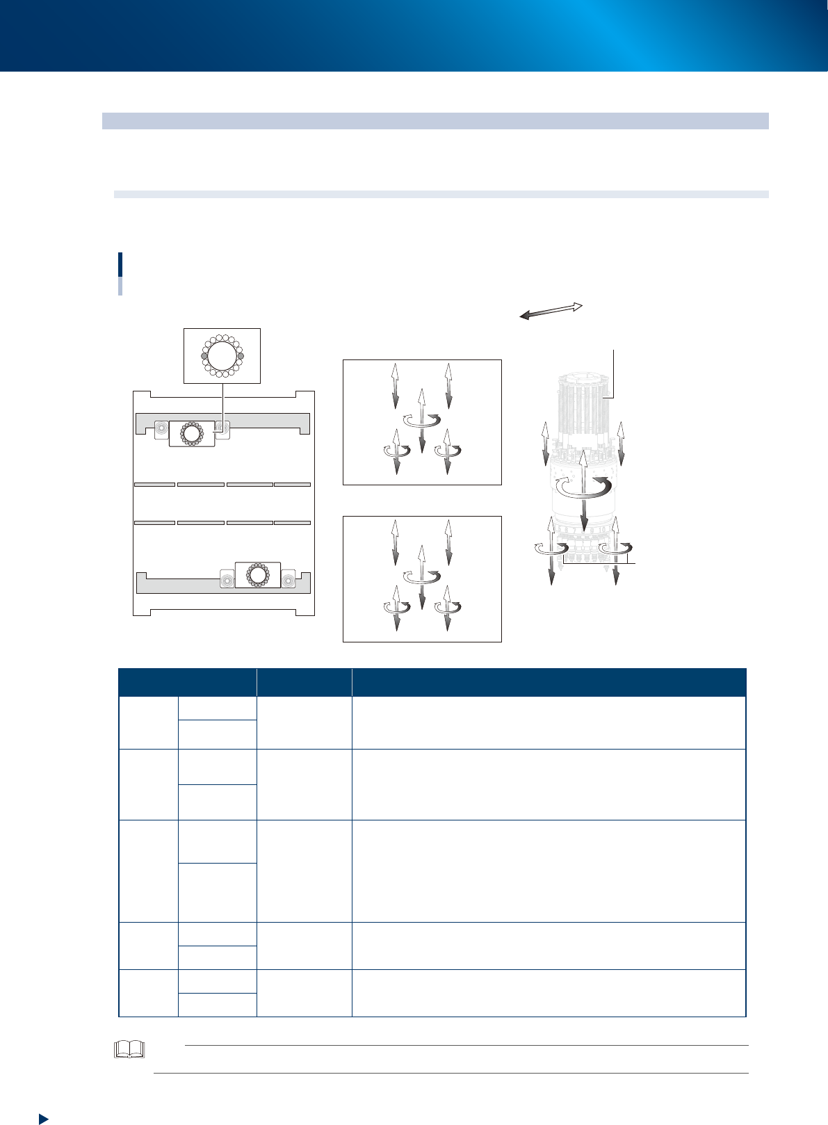
7.1.1 RM head unit
1
1
110
2
18
Head axes configuration of RM head unit
Example as viewed from the machine front
Plus direction
Minus direction
R-axis
Z1-axis
Z2-axis
V1-axis
V2-axis
N-axis
HZ-axis
Front side / Head unit A
Rear side / Head unit B
Rotary
ZA2-axis
RA-axis
ZA1-axis
RA-axis
HZA-axis
NA-axis
VA2-axis
VA1-axis
ZB1-axis
RB-axis
ZB2-axis
RB-axis
HZB-axis
NB-axis
VB1-axis
VB2-axis
Head unit A
Machine front
Head unit B
23137-KMX-00
Axis Specification Function
Z-axis
ZA1, ZA2
Linear motor
Are located at both sides of RM head unit. The components are
picked-up/mounted by ascending/descending the one of 18 nozzle
shafts installed in rotary. Z1-axis is also called rod 1, and Z2, rod 2.
ZB1, ZB2
V-axis
VA1, VA2
Linear motor
Are located at both sides of RM head unit.
The stroke of V-axis is narrower than that of Z-axis. V-axis performs
vacuum/air supply switching for nozzle shaft by ascending/descending
the mechanical valve (spool) of rotary.
VB1, VB2
HZ-axis
HZA
Linear motor
Moves the whole RM head unit up-and-down.
It supports the Z-axis motion upon component picking-up/mounting to
shorten mounting time. Also, the RM head unit ascends upon picking-
up a thick component. Moreover, it ascends to fit to component size,
upon recognizing components, to adjust multi-view camera focus.
Downward is plus direction.
HZB
R-axis
RA-
axis
Motor & gear
Rotates all 18 nozzle shafts inside the rotary at the same time.
The counterclockwise, viewed from above, is plus direction.
RB-
axis
N-axis
NA-
axis
Motor & gear
Rotates whole rotary.
The clockwise direction, viewed from above, is plus direction.
NB-
axis
TIP
The front head unit is called "head unit A", and the rear, "head unit B".
7. Axis configuration
1-63
Chapter 1 Unit names and functions
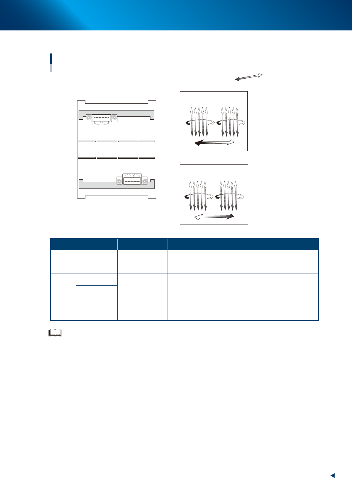
7.1.2 HM head unit
10
1
1
10
Head axes configuration of HM head unit
Example as viewed from the machine front
Plus direction
Minus direction
RA1-axis
RB1-axis
RA2-axis
RB2-axis
SCB-axis
SCA-axis
Front side / Head unit A
ZB1ZB10 ZB6 ZB5
ZA10ZA1 ZA5 ZA6
Head unit A
Machine front
Head unit B
Rear side / Head unit B
23138-KMX-00
Axis Specification Function
Z
axis
ZA1 to ZA10
Linear motor
Moves up-and-down the picking-up/mounting heads.
The downward is plus direction.
ZB1 to ZB10
R
axis
RA1, RA2
Motor and timing
belt
Rotates 5 nozzle shafts as unit using 2 motors, R1 and R2.
The counterclockwise, viewed from above, is plus direction.
RB1, RB2
SC
axis
SCA
Linear motor
Moves scan camera from side to side.
The direction from the head No. 1 to the No. 10 is plus
direction.
SCB
TIP
The front head unit is called "head unit A", and the rear, "head unit B".
7. Axis configuration
1-64
Chapter 1 Unit names and functions
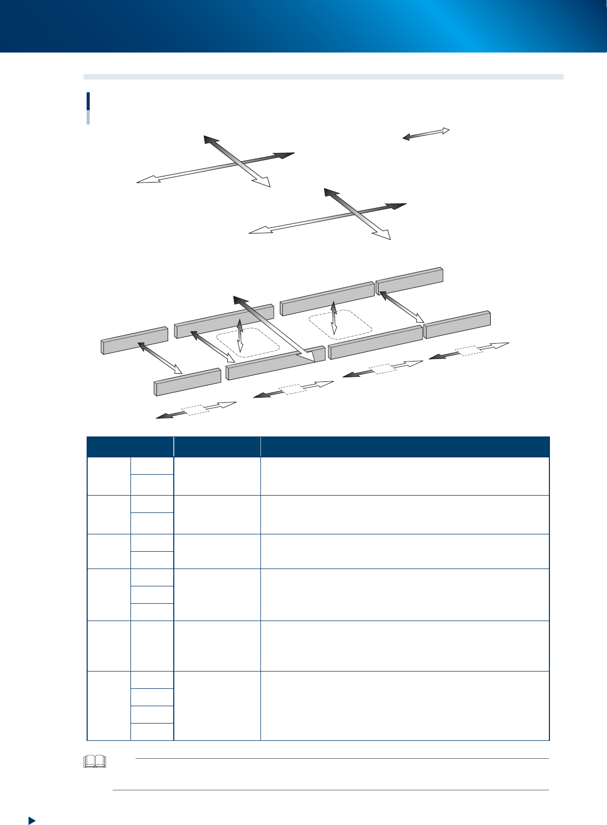
7.2 Main axis and conveyor axis configuration
W1&W2-axis
YB-axis
YA-axis
XA-axis
XB-axis
W4-axis
U-axis
Main-axis and conveyor-axis configuration
■ Main axes
■ Conveyor axes
Mounting stage 2
Mounting stage 1
Exit conveyor
W3-axis
PU2-axis
PU1-axis
CV2-axis
CV3-axis
CV4-axis
CV1-axis
Plus direction
Minus direction
23139-KMX-00
Axis Specification Function
X-
axis
XA
Motor and boll
screw
Moves the head unit parallel to the board carrying direction of
conveyor.
The rightward viewed from front is plus direction.
XB
Y-
axis
YA
Linear motor
Moves the head unit to right angle of the board carrying direction of
conveyor.
The rearward is plus direction.
YB
PU-
axis
PU1
Motor and timing
belt
Ascends the push-up plate.
The upward is plus direction.
PU2
W-
axis
W1&W2
Motor and timing
belt
Changes the conveyor width.
The direction of conveyor widening is plus direction.
W3
W4
U-
axis
-
Motor and timing
belt
Moves the whole mounting stage 2 to Y direction. The rearward is plus
direction.
It shorten the mounting time by putting close the head unit and the
component mounting position.
CV-
axis
CV1
Motor and timing
belt
Drives conveyor belt to carry the boards.
The direction of carriying the board from right to left is plus direction.
CV2
CV3
CV4
TIP
•The conveyor width changing axis (W2-axis) and W1-axis of the mounting stage 1 are driven together by one motor.
•The front head unit is called "head unit A", and the rear, "head unit B".