YRM20_Ope_E.pdf - 第161页
4. Preparing component tape 2-64 Chapter 2 Basic o pera tion 4.1.4 Setting board data of component tape After completing setting up the feeder on the machine main bod y , set the tape feed pitch in the board data on the …
4. Preparing component tape
2-63
Chapter 2 Basic operation
3
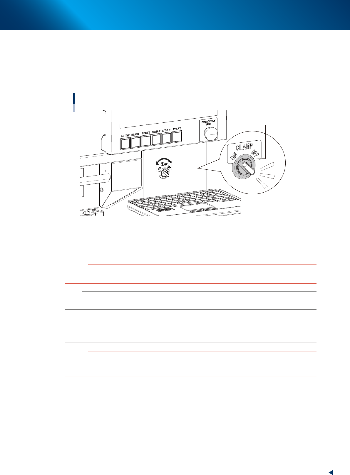
Turn the clamp switch ON.
Turn the clamp switch corresponding the position where the carriage is inserted to left (ON), then the
carriage clamp unit at the mounter side moves down to clamp the carriage.
The LED indicator of the clamp switch starts blinking during clamping the carriate.
After that, the communication is checked automatically between the mounter, the carriage and the
feeders.
Carriage clamp switch
Clamping : Indicator blinks
Clamp switch
23219-KMX-00
4
Check the clamp switch light is on.
After the communication check between the mounter, the carriage and the feeders are completed, the
switch indicator is changed lighting. Unhold the carriage handles.
c
CAUTION
While the clamp switch is blinking, do not touch the inside of machine or carriage.
The clamp unit moving down might pinch hands.
n
NOTE
While the safety cover or the upper cover of the mounter is open, the clamp unit doesn't move down even with turning the
clamp switch.
n
NOTE
There is the sensor called "forward end sensor(FDR FORWARD SENSOR)" at far end of the carriage set position of the
mounter. When the carriage is inserted to far end, this sensor recognizes. When this sensor doesn't recognize the carriage,
the clamp units doesn't move down even with turning the clamp switch.
c
CAUTION
The deviation of carriage during clamping motion loads the clamp connector and the repetition of this motion may damage
the clamp connector.
Make sure to keep firmly the carriage handles to attach the carriage.
4. Preparing component tape
2-64
Chapter 2 Basic operation
4.1.4 Setting board data of component tape
After completing setting up the feeder on the machine main body, set the tape feed pitch in the board data
on the machine main body.
1
Check the component tape feed pitch.
Check the component tape feed pitch prior to the operation.
2
Call up the [Parts] – [Basic] screen.
Read out the board data. Call up the [Parts] – [Basic] tab screen.
3
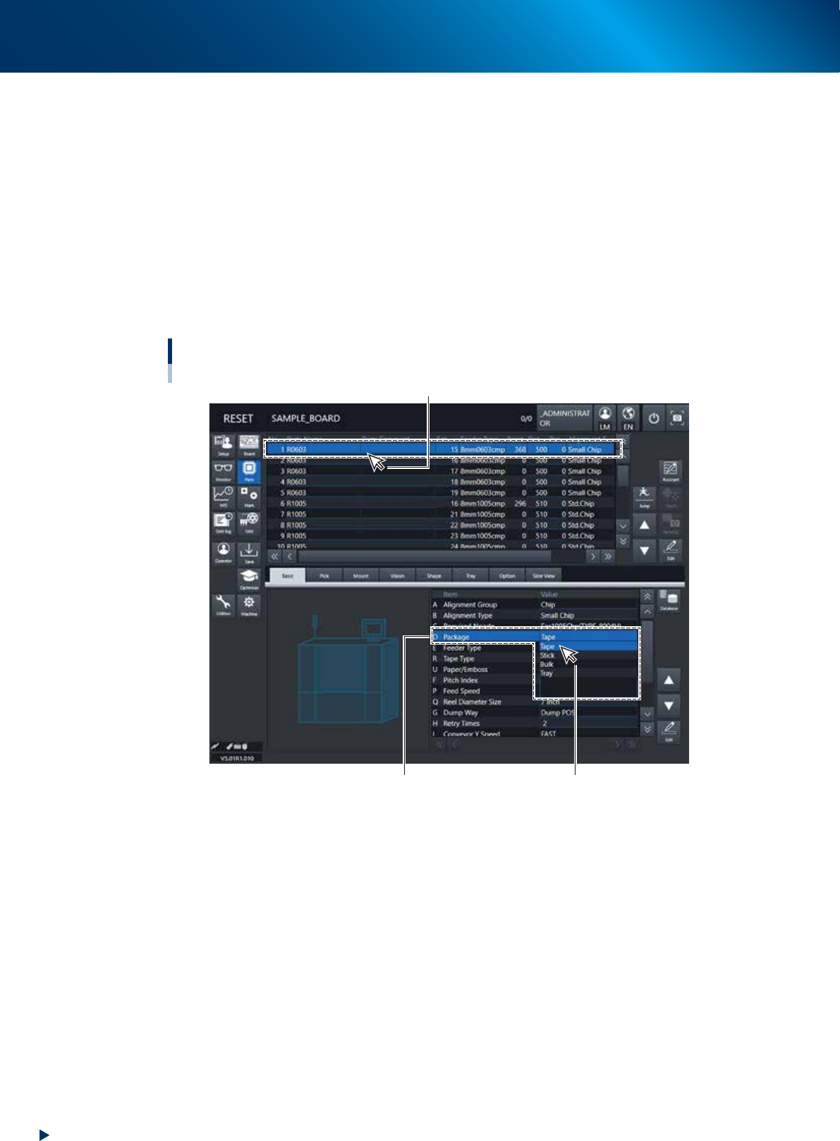
Specify the “Package”.
Select the components to specify the parameters for. Pull down “D. Package” and select “Tape”.
Setting up board data / Component tape
[Parts] - [Basic] tab
D. Package
Select “Tape”.
Select the components to specify the parameters for.
24229-KMX-00
4. Preparing component tape
2-65
Chapter 2 Basic operation
4
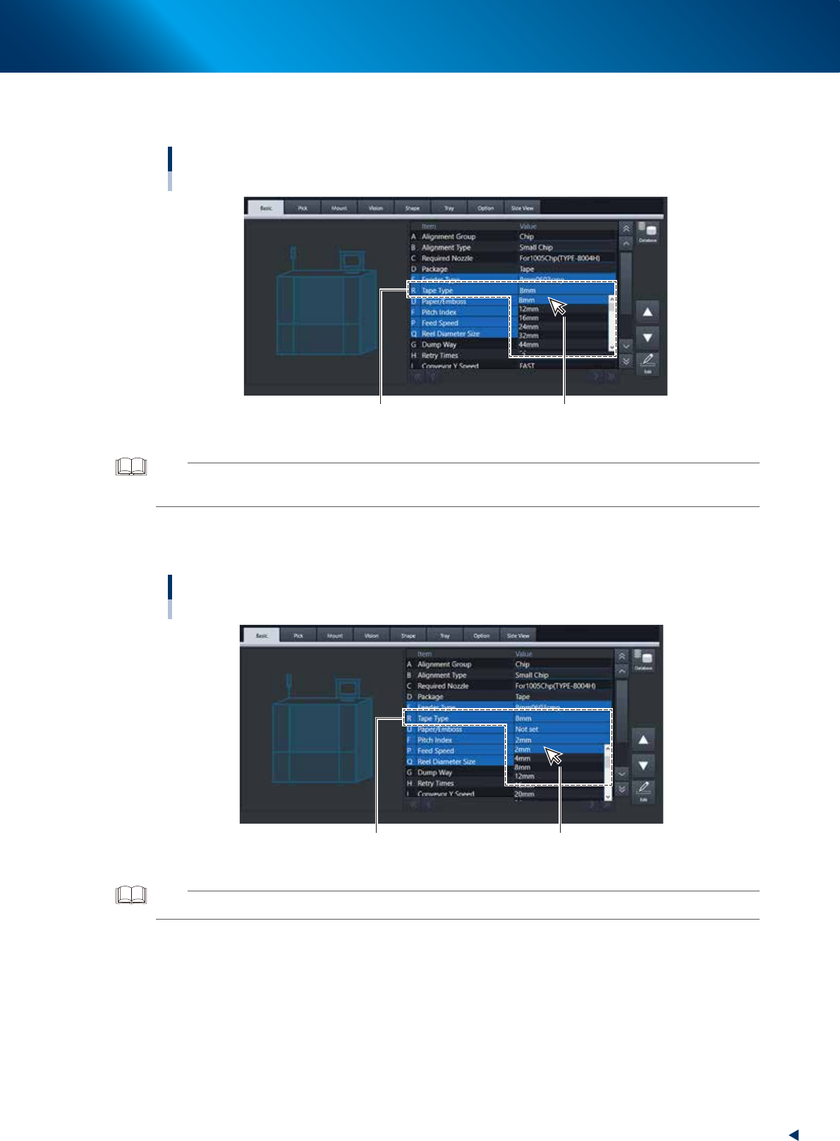
Specify the “Tape type”.
Drop down “R. Tape Type” to select the type of component tape.
Setting up board data / Component tape
[Parts] - [Basic] tab
R. Tape Type Select from the drop-down list.
24230-KMX-00
TIP
• Changing “D. Package” also changes “R. Tape Type”.
• The setting of “E. Feeder Type” is not provided.
5
Specify “Pitch Index”.
Drop down “F. Pitch Index” to select the feed pitch according to the component tape to be used.
Specifying the Pitch Index
[Parts] - [Basic] tab
F. Pitch IndexSelect from the drop-down list.
F. Pitch Index Select from the drop-down list.
24231-KMX-00
TIP
See the “ZS/ZSR FEEDER User’s Manual” for the details.