YRM20_Ope_E.pdf - 第112页
2. Operation screen and buttons 2-15 Chapter 2 Basic operation 2.2 Setup scr een T his section describes the operation buttons displa yed on the "Setup" screen. Setup screen 18 19 20 23 22 21 3 4 9 10 11 16 8 1…

2. Operation screen and buttons
2-14
Chapter 2 Basic operation
4. [BUZZER OFF]
Turns off the buzzer.
5. [ERROR CLEAR]
Clears the error that has occurred.
6. [Close] button
Closes the error screen without clearing the error.
TIP
The positions where errors occurred can be checked graphically by opening the [Monitor] - [Production] tab after closing
the error screen by pressing the [Close] button. Pressing the [Error Detail] button on the [Production] screen redisplays the
error message. See"3.1 Production" in this chapter for the [Production] screen.
2. Operation screen and buttons
2-15
Chapter 2 Basic operation
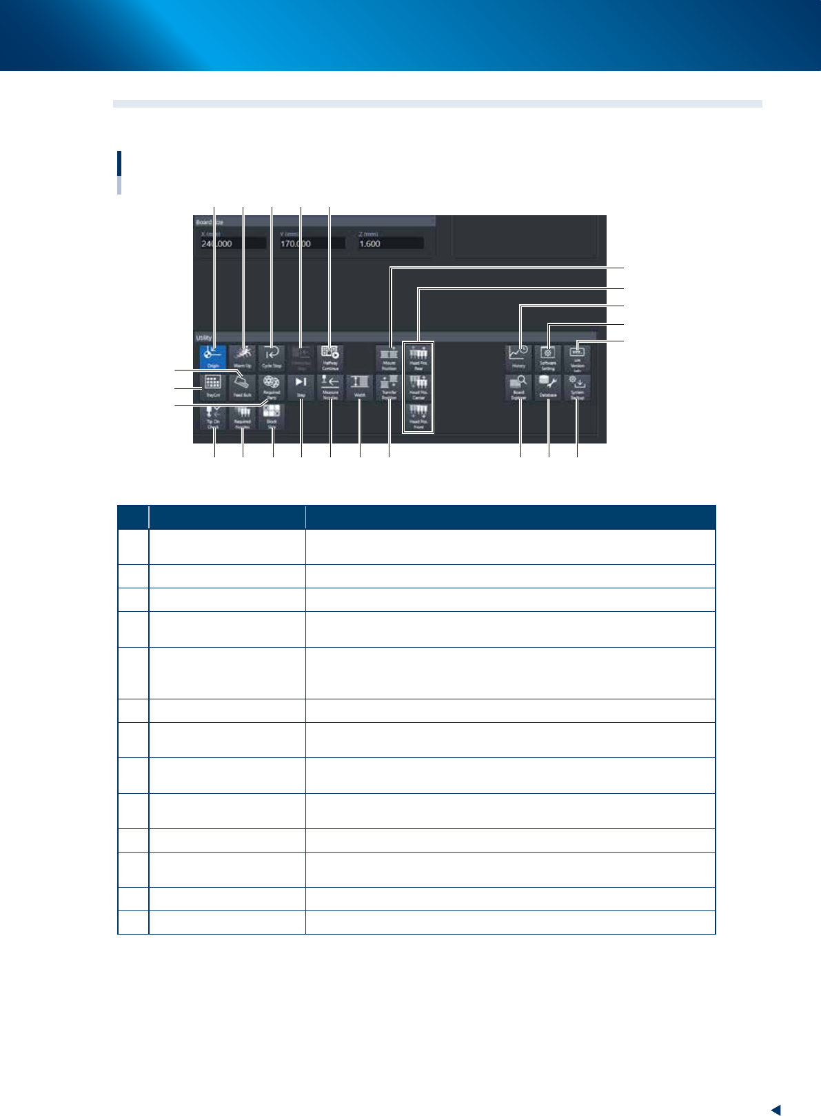
2.2 Setup screen
This section describes the operation buttons displayed on the "Setup" screen.
Setup screen
18
19
20
23
2221
3 4
9 10
11
16
8
12
7
6
15
17
51 2
13 14
24204-KMX-00
Button name Function
1 Origin
Move all the axes other than the W-axis of the machine to their respective
origins.
2 Warm Up Warms up the machine. Specifying the desired time is available.
3 Cycle Stop Stops the machine without flowing a mounted board to downstream.
4 Convey-out Stop
Stops machine operation after mounting components on all boards on the
conveyor and transferring them to the downstream machine.
5 Halfway Continue
Resumes mounting components on the board that reset the suspended
machine operation due to an error. See chapter 3, "1.12 Resuming
operation from the stopped point" for more details.
6 Tray Cnt Displays the number of tray components that have been used.
7 Feed Bulk
This button is operable only when using the bulk feeder (custom-made). It
is not used in normal operation.
8 Required Parts
Displays the component types and feeder positions that are set up for the
production to be started.
9 Step
Temporarily stops the machine at a specific position, for example, during
initial component mounting, test mounting, or trouble analysis.
10 Measure Nozzles The scan camera (side view camera) acquires the nozzle shape.
11 Width
Aligns the conveyor width with the board surface for production. It is the
same function as the [Width] button of the [Unit] – [Conveyor] screen.
12 Tip Cln Check Checks if nozzle tips are dirty or clogged.
13 Required Nozzles Displays a list of nozzles to be used.
2. Operation screen and buttons
2-16
Chapter 2 Basic operation
Button name Function
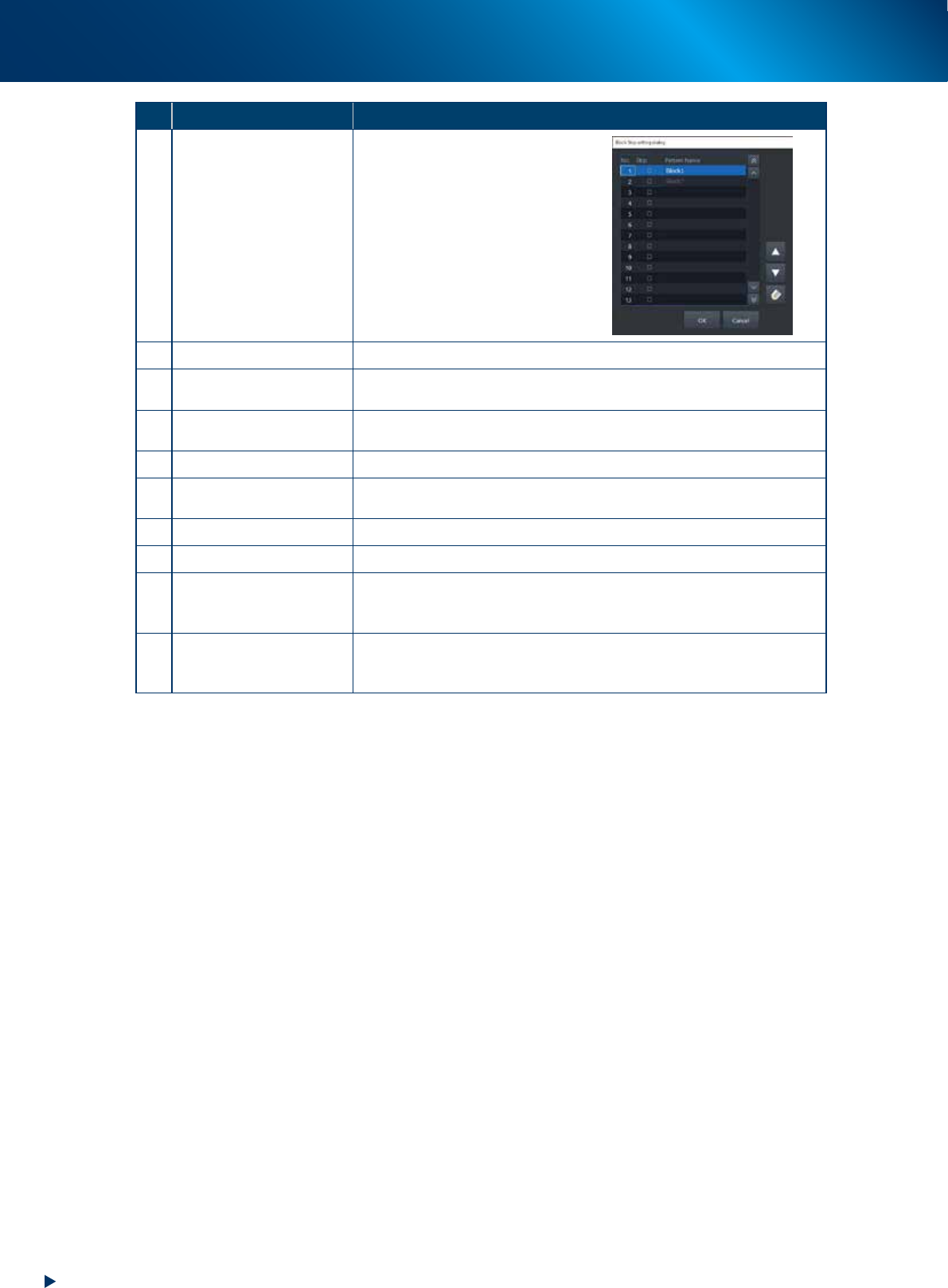
14 Block skip
This button becomes active when
board data with block distribution
performed is loaded.
Pressing this button displays the
"Block Skip Utility" dialog box that
allows you to set whether to skip
mounting components in each
block.
Refer to Chapter 3 "1.12
Resuming operation from the
stopped point" for more details.
15 Mount Position Moves the conveyor to the mounting position for the backup pin setup.
16 Transfer Position
Aligns the conveyor with the transfer position when carrying in the board
manually.
17
Head movement
(rear, center, front)
Moves head to the machine rear, center, or front.
18 History Saves and deletes production history data.
19 Software Setting
Sets machine screen display items, adds or deletes operators, and sets
passwords.
20 SW Version Info Shows version information on application software and system.
21 Board Explorer Moves, backs up, restores or copies board data.
22 Database
Makes a backup of and restores database regarding components required
for production and mark information. Also it can specify the database
reference destination.
23 System Backup
Makes a backup of machine coordinates, accuracy information, option
device information and standard coordinates necessary for machine
operation or restores the data using the backup.