YRM20_Ope_E.pdf - 第192页
1. Flow from starting up machine to production 3-12 Chapter 3 Flow from starting up machine to production 2 Lift the m ain stopp er . Lift the main stopper to place the board at the board mounting posi tion. Press the [M…
1. Flow from starting up machine to production
3-11
Chapter 3 Flow from starting up machine to production
1.6.1 Laying out push-up pins
c
CAUTION
The procedure described in this section requires the conveyor unit and push-up plate to actually operate to get ready for
production. Before starting the procedure in this section, be absolutely sure to check the conveyor and its peripherals
according to "1.1 Pre-operation check" in this chapter.
1
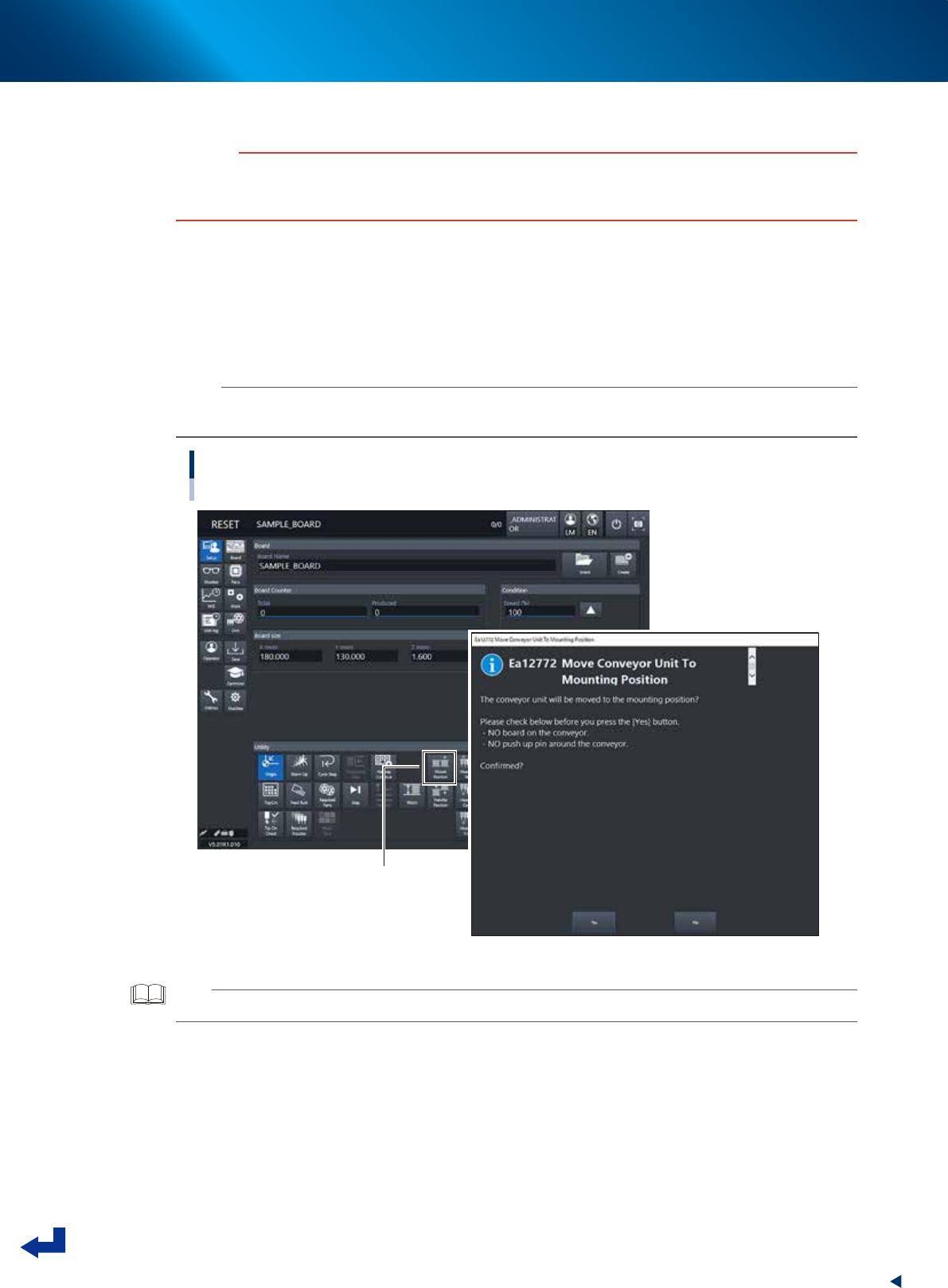
Move the conveyor to the mount position.
1. Press [Mount Position] button in [Setup] screen.
2. The message "Move Conveyor Unit To Mounting Position" is displayed, and then press the [Yes]
button.
The conveyor width changes to that specified in the board data, and then the mounting stage 2
moves to the mount position.
n
NOTE
When the board is of L=380mm or less, the mounting stage 2 moves to machine rear side.
Otherwise, the mounting stage does not move upon using the board of more than L=380mm.
Moving to the mount position
[MountPosition] button
24307-KMX-00
TIP
Pressing [Mount Position] also makes the conveyor width changed to the width specified in the board data.
1. Flow from starting up machine to production
3-12
Chapter 3 Flow from starting up machine to production
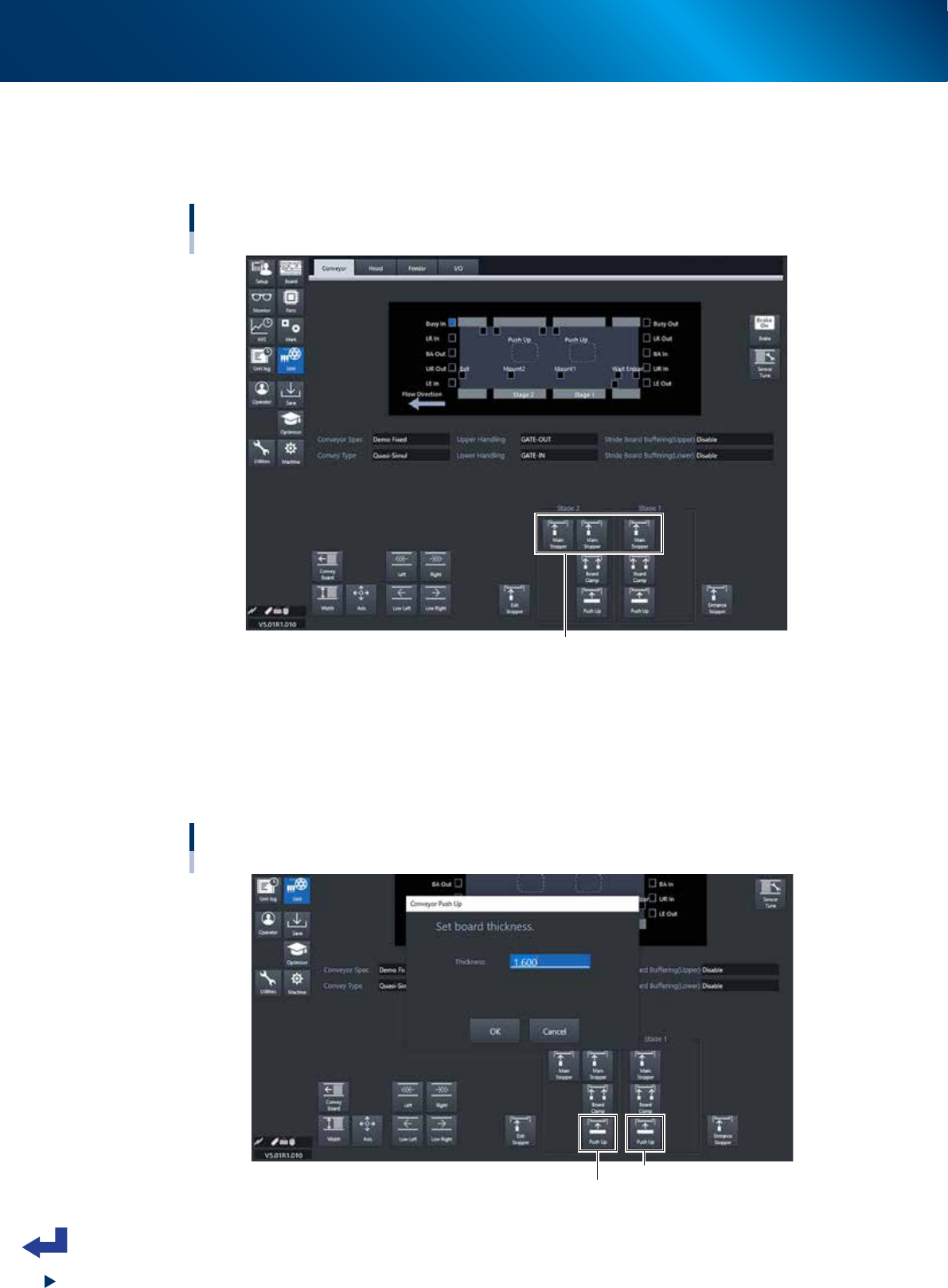
2
Lift the main stopper.
Lift the main stopper to place the board at the board mounting position.
Press the [Main Stopper] button on the “Unit” – “Conveyor” screen to lift the main stopper.
Press the [Main Stopper] buttons for both of stage 1 and stage 2 to lift the main stoppers.
Lifting the main stopper
[Unit] - [Conveyor] screen
[Main Stopper] button
24308-KMX-00
3
Move up the push-up plate.
1. Press [Push Up] button on [Unit] - [Conveyor] screen. Then "Conveyor Push Up" screen appears.
2. Press [OK] button after confirming the board thickness is correct. Then push-up plate moves up.
3. Move up the push-up plates for both stage 1 and stage 2 by following the procedure 1 and 2
above.
Moving up the push-up plate.
[Unit] - [Conveyor] screen
Stage 1 [Push Up] button
Stage 2 [Push Up] button
24309-KMX-00
1. Flow from starting up machine to production
3-13
Chapter 3 Flow from starting up machine to production
4
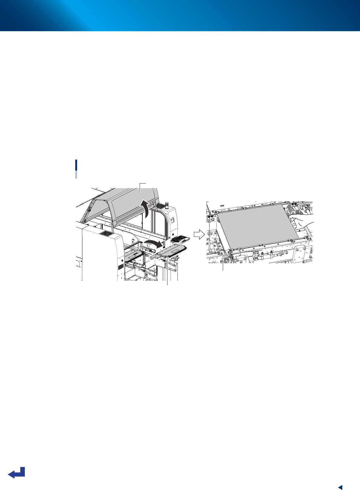
Lay out the push-up pins.
Fix the push-up pins on the push-up plate with magnets.
e
1. Press the [EMERGENCY STOP] button.
2. Unclampe the feeder exchange carriage and detach it.
3. Open the machine safety cover, and remove the upper cover when needed.
4. Temporarily place the board on the conveyor of mounting stage 1, so that the board edge
contacts to main stopper.
5. Confirm the board size (meaning the area where the push-up pins are placed), and then
temporarily remove the board.
6. Lay out the push-up pins on the push-up plate so that the whole board including its edge are
held evenly by the pins. Be careful not to touch the components if they are mounted on the back
side of the board already.
7. Lay out the push-up pins of the mounting stage 2 by the same procedures.
Temporarily placing the board
Mounting stage 1 as example
Main stopper
Safety cover
Upper cover
23303-KMX-00