YRM20_Ope_E.pdf - 第198页
1. Flow from starting up machine to production 3-18 Chapter 3 Flow from starting up machine to production 4 A djust the bo ard hold plat e on th e mout ing stage 2 . 1. Close the upper cover and safety cover . 2. Attach …
1. Flow from starting up machine to production
3-17
Chapter 3 Flow from starting up machine to production
e
3
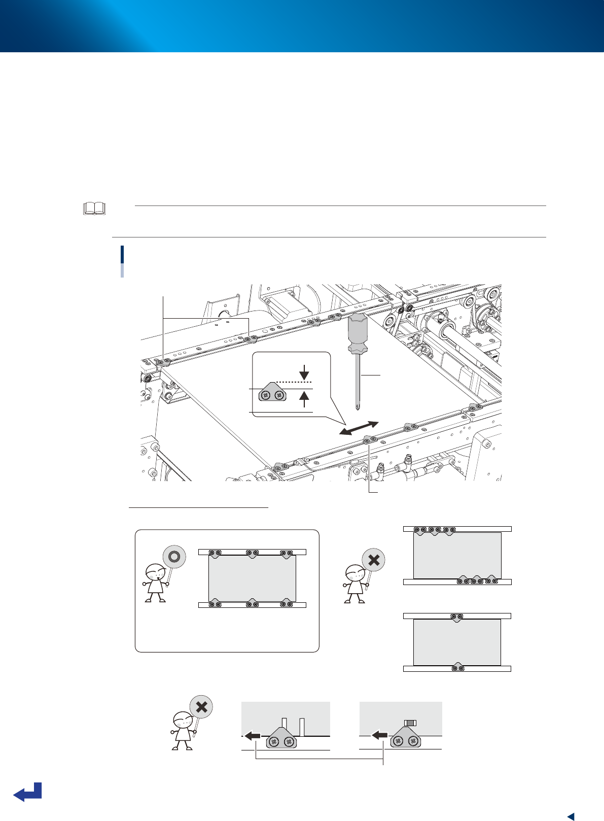
Adjust the board hold plate positions.
1. Press the [EMERGENCY STOP] button.
2. Unclamp the carriage and detach it.
3. Open the machine safety cover, and remove the upper cover when needed.
4. Loosen the screws on the board hold plates with Phillips screw driver. It is not required to
detach them.
5. Move the board hold plates to the side according to the size and shape of the board.
6. Tighten the screws on the board hold plates.
TIP
The board hold plate overlaps the board by 3 mm (the length of the portion of the board hold plate over the board is 3
mm).
Adjusting the board hold plate positions
Dual stage : Stage1
Phillips screw driver
Board hold plates
Loosen screws to slide board hold plate.
• Board hold plates are not uniformly laid out.
• Board hold plate is too close to a
component mounting position.
Tips for adjusting the board hold plates
• Board hold plates are uniformly laid out.
• There is no obstacles such as a slit near to plate.
• The number of plates is insufficient.
• Board hold plate holds
a portion with a slit.
Slide the board hold plate.
3mm
23305-KMX-00
1. Flow from starting up machine to production
3-18
Chapter 3 Flow from starting up machine to production
4
Adjust the board hold plate on the mouting stage 2.
1. Close the upper cover and safety cover.
2. Attach the feeder exchange carriage.
3. Release [EMERGENCY STOP] button.
4. Press the [Convey Board] button in [Unit] - [Conveyor] screen.
5. The "Convey Boards" check screen appears, so confirm "All position" is ticked, and then press
the [OK] button.
6. The "CONVEYOR AND FIX" message appears, then press the [OK] button twice. The board is
conveyed from the mounting stage1 of upstream to the mounting stage 2 of downstream, and
the board is fixed at its mounting position of mounting stage 2.
7. Adjust the board hold plate position on the mounting stage 2 by Step 2 and Step 3.
5
Remove the board.
1. Close the upper cover and safety cover.
2. Attach the carriage.
3. Release the [EMERGENCY STOP] button.
4. Press the [Convey Board] button on [Unit] - [Conveyor] screen.
5. The "Convey Boards" check screen appears, so confirm "All position" is ticked, and then press
the [OK] button.
6. The "CONVEY AND FIX" screen appears, the press the [OK] button. The board is transferred to
the exit conveyor.
7. Remove the board manually.
TIP
Here, the board is conveyed in "All position". When the "Specify Position" is ticked on the "Convey Boards" screen and
then, either of "Entrance", "Upstream mounting position", "Downstream mounting position" or "Exit" is selected for "Start
Pos./Target Pos.", the board is conveyed only in the specified path.
1. Flow from starting up machine to production
3-19
Chapter 3 Flow from starting up machine to production
1.6.3 Checking condition of clamping board
1
Enter the board.
See step 1 in"1.6.2 Adjusting board hold plate position" to convey the board in the same way.
e
2
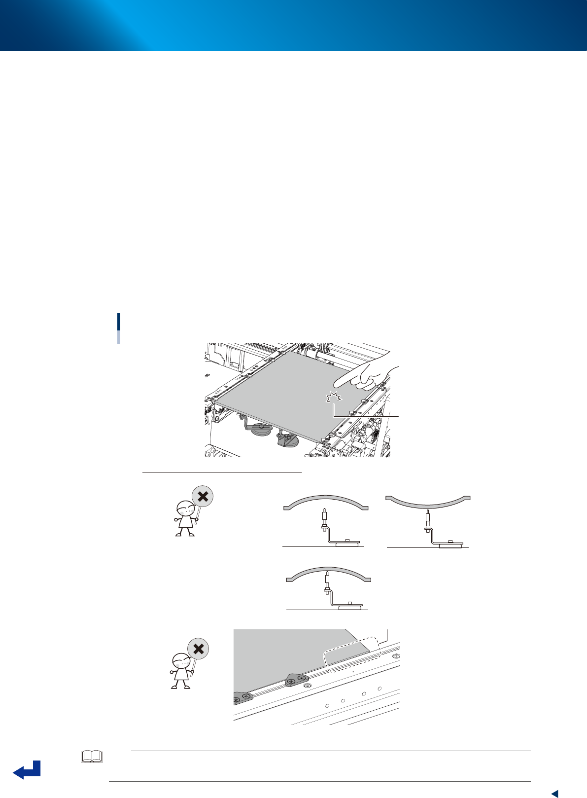
Check the board clamping condition.
1. Press the [EMERGENCY STOP] button.
2. Unclamp the carriage and detach it.
3. Open the machine safety cover, and remove the upper cover when needed.
4. Knock the several points on the board lightly with the finger and visually check the board from
side to see that the push-up pins evenly support the board.
5. Visually check the board from side to see that the board doesn't warp excessively downwards
or upwards.
6. (Especially around the left and right edges of the board) Check that the board doesn't lift or
sag from the conveyor frame.
7. If it is found that the board is not clamped well by checked in 4 to 6 above, adjust the locations
of push-up pins and board hold plates or add the push-up pins to correct the condition and
recheck.
Checking the condition of clamping board.
Knock lightly on board
with fingertip
How to check the condition of clamping board
• “Board thickness” setting is incorrect.
• Locations of push-up pins are not suitable for warp of board.
• “Board thickness” setting is incorrect.
• Locations of board hold plates are incorrect.
Board edge is lifted.
23306-KMX-00
TIP
The allowable warp of component mounting boards for YRM20 is 0.5 mm or less upwards and 1.0 mm or less
downwards.