YRM20_Ope_E.pdf - 第62页
3. Head unit 1-31 Chapter 1 Unit names and functions 3.4.4 Shaft blow dump of very small components Regarding to disposal of very small components less than 0603 size on this mac hine, if some components or dust are reco…
3. Head unit
1-30
Chapter 1 Unit names and functions
█
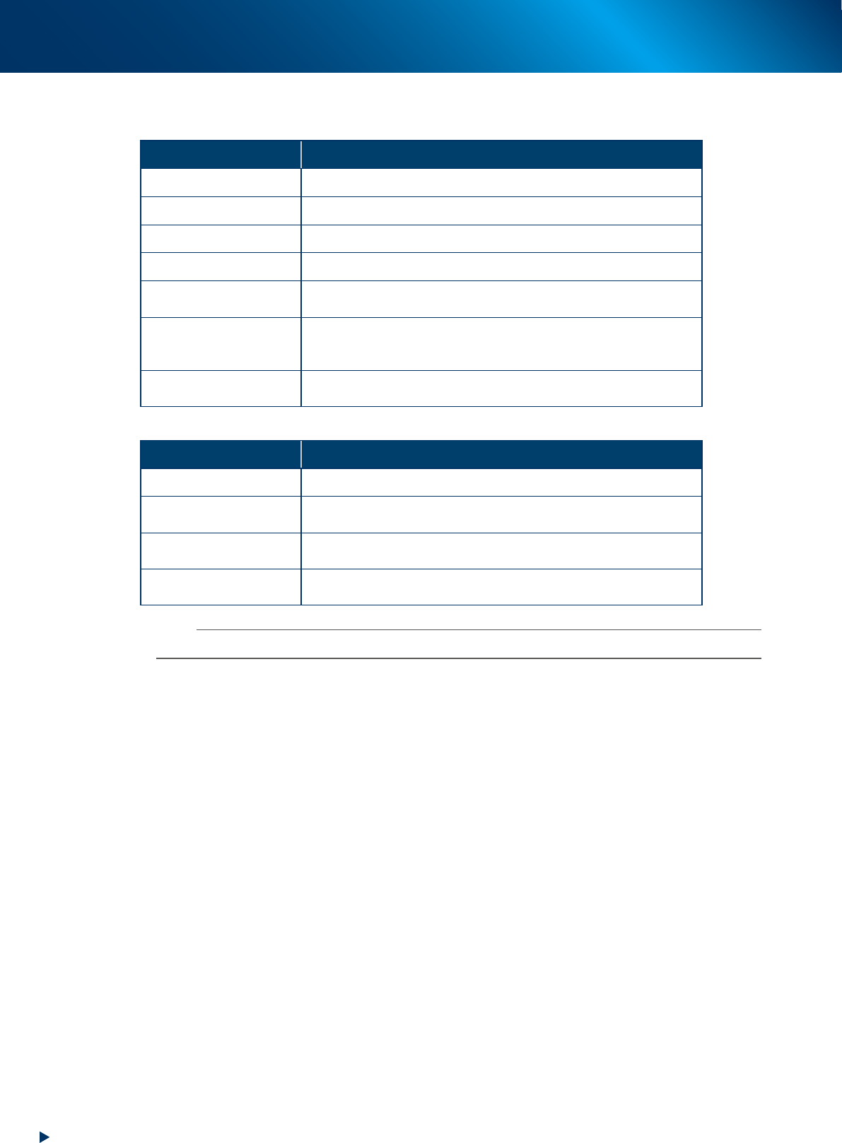
“Executive Condition” and “Cycle Condition” of nozzle shaft blow
►
Executive Condition
Executive Condition Operation
None The automatic nozzle shaft blow is not performed.
Power On The nozzle shaft blow is performed after powering on the machine.
Power Off The nozzle shaft blow is performed before powering off the machine.
Reset The nozzle shaft blow is performed at the time of resetting.
Start Run
The nozzle shaft blow is performed when starting up the automatic
operation.
Lot Start+Auto Running
The nozzle shaft blow is performed at the time of starting up the
automatic operation after loading the board data according to the set
cycle condition.
Only Auto Running
The nozzle shaft blow is performed according to the set cycle
condition.
►
Cycle Condition
Cycle Condition Operation
None No cycle condition applies.
Minute Unit
The nozzle shaft blow is performed according to the pre-set time
interval (minutes).
Every Day
The nozzle shaft blow is performed at the pre-set time of every day
when the machine is in the automatic operation.
Every Week
The nozzle shaft blow is performed at the pre-set time of the day of
the week when the machine is in the automatic operation.
n
NOTE
Setting the multiple times is available with the “Multi Interval Setting”.
3. Head unit
1-31
Chapter 1 Unit names and functions
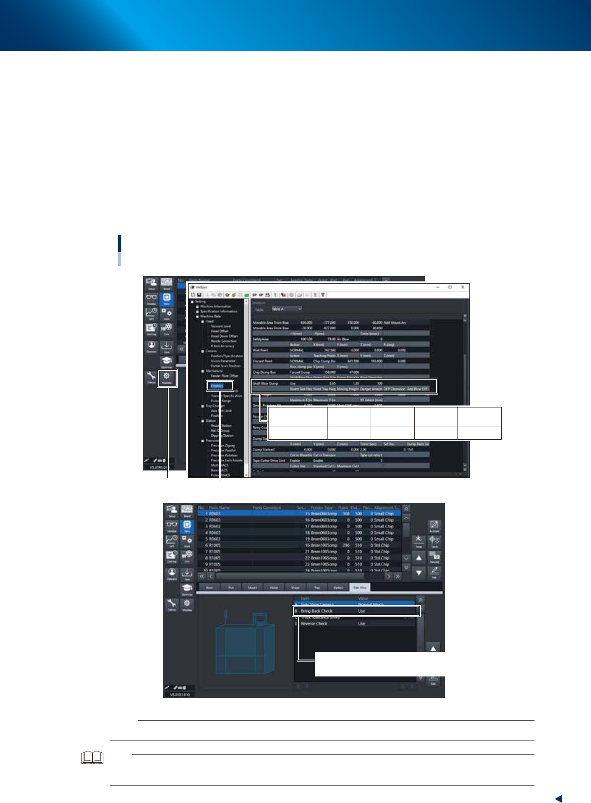
3.4.4 Shaft blow dump of very small components
Regarding to disposal of very small components less than 0603 size on this machine, if some components or
dust are recognized at checking after disposing operation, the air-blow station continues the shaft blow dump.
The target components for the shaft blow dump are determined by the following three settings.
1. The machine is equipped with the air-blow station.
2. The function of the shaft blow dump is set "Use" in "Machine Data"-"Mechanical"-"Position" and
"Dump Size" and "Blow Timer" are appropriately set.
3. The size of the component to be disposed of is less than the setting value in 2.
Additionally, to check the disposal, if "B: Bring Back Check" in [Parts]-[Side View] is set with "Use", the side
view camera is used for judgement. If it is set with "Not Use", the vacuum pressure check is used for
judgement.
Setting the Shaft Blow Dump
Board data : [Parts] - [Side View]
Setting : “Machine Data” - ”Mechanical” - “Position”
[Machine] button
“Mechanical” - ”Position”
B Bring Back Check/Use : Judged by the side view camera
Bring Back Check/ Not Use : Judged by the vacuum pressure
Shaft Blow Dump
Dump Size
X (mm)
0.65
Dump Size
Y (mm)
1.30
Shaft Blow
Dump
Use
Blow Timer
(msec)
100
24108-KMX-00
n
NOTE
The shaft blow dump doesn't work if "Shaft Blow Dump" is set with "Not Use", "Dump size" is "0" or "Blow timer" is "0".
TIP
The setting in the figure above is the recommended setting that the shaft blow is only applicable for small components of
size 1005.
3. Head unit
1-32
Chapter 1 Unit names and functions
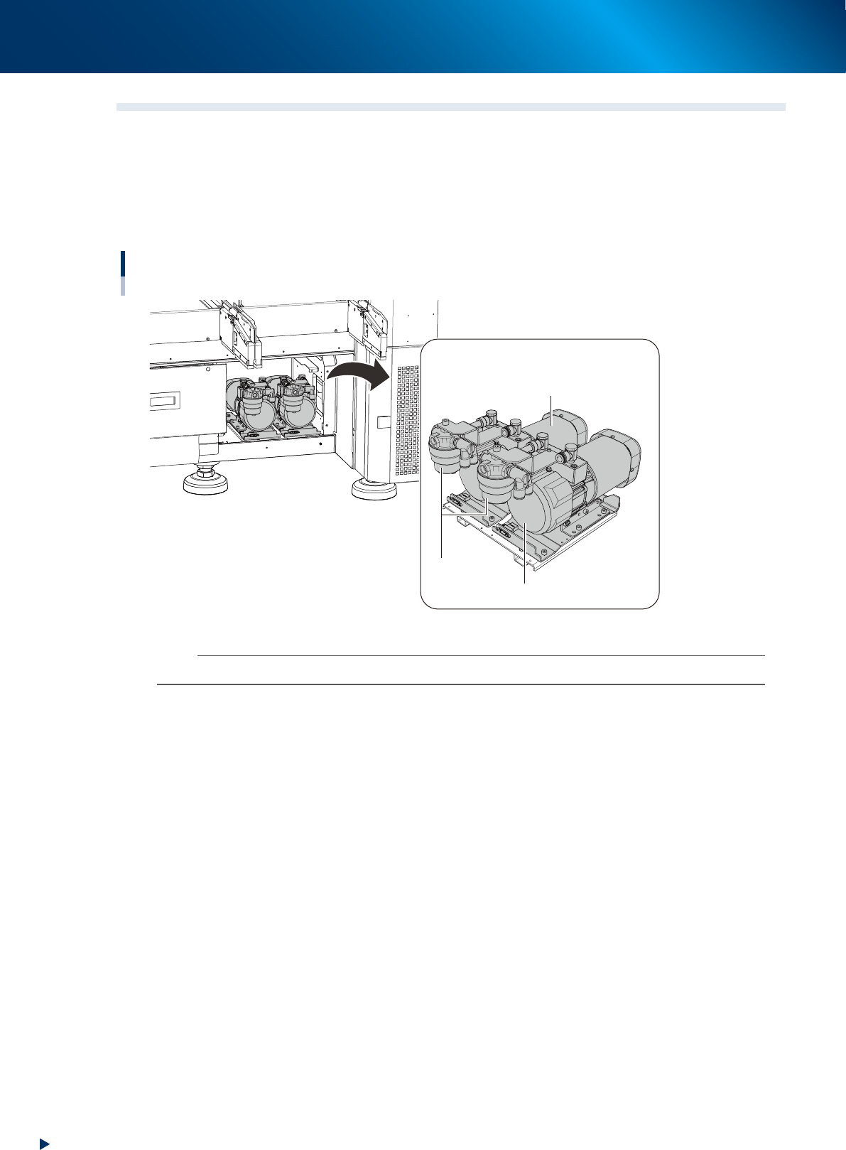
3.5 Vacuum pump ( RM head)
3.5.1 Vacuum pump (RM head)
RM head unit generates vacuum for component pick-up by vacuum pump.
The vacuum pump is installed at the inside of machine rear panel.
The vacuum pump located at rear left of machine, viewed from front, works for front head unit, and the
other, for rear head unit (the figure below is viewed from machine rear).
Vacuum pump (RM head unit)
Vacuum pump
For rear RM head unit
For front RM head unit
Filter
23120-KMX-00
n
NOTE
HM head unit generates vacuum for component pick-up by ejector of head unit.