YRM20_Ope_E.pdf - 第191页
1. Flow from starting up machine to production 3-11 Chapter 3 Flow from starting up machine to production 1.6.1 Laying out push-up pins c CAUTION The procedure descri bed in this section requi res the conveyor unit and p…
1. Flow from starting up machine to production
3-10
Chapter 3 Flow from starting up machine to production
1.6 Conveyor unit setup
Set up (Get ready) the conveyor unit according to the selected board data.
The following 3 tasks for setting up the conveyor unit are required– “Push-up pin layout”, “Adjusting board
hold plate position” and “Checking state of clamping board”.
█
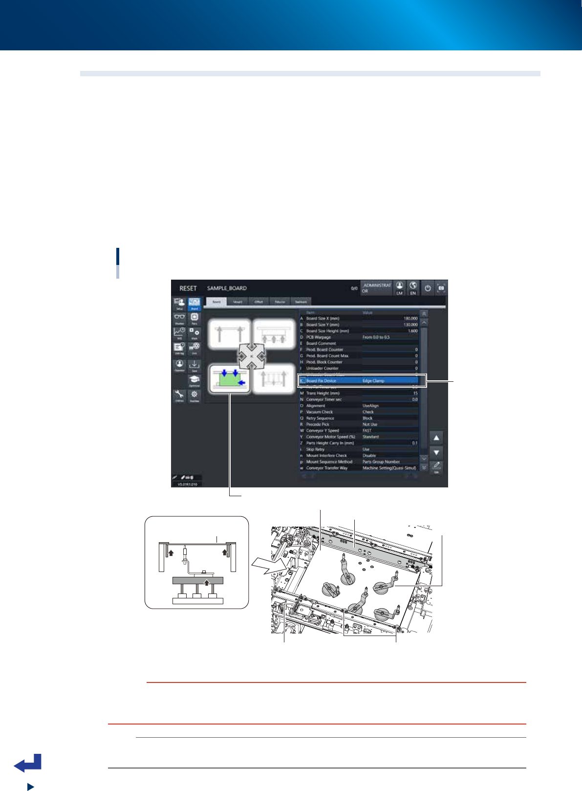
Board clamping method
Normally, the machine follows the “Edge clamp” method to clamp a board. The procedure is as follows.
1. The board transferred on conveyor stops at the mounting position when it comes into contact with the
main stopper.
2. The clamp board assembly pushes up the edge of the board so that the board is secured in place
between the clamp board assembly and the board hold plate.
3. Other than the edge of the board, the push-up pins support the board from under.
Board clamping
method
Board clamping method
C. Push-up pins
A. Push-up plate
B. Clamp board assembly
Main stopper
Figure of clamped board
D. Board hold plate
Board
BB
DD
C
A
Figure of clamped board (side view)
24306-KMX-00
c
CAUTION
If the board to be processed has a slit or the like, some of the conveyor sensors might not be able to detect the board. In
such a case, changing the machine settings and adjusting the sensor positions might be required. Before starting the actual
production, make absolutely sure that the boards are transferred correctly as intended.
n
NOTE
This machine follows the “Edge clamp” method to clamp a board. If using other method to clamp the board, the machine
may need to be modified or evaluated.
1. Flow from starting up machine to production
3-11
Chapter 3 Flow from starting up machine to production
1.6.1 Laying out push-up pins
c
CAUTION
The procedure described in this section requires the conveyor unit and push-up plate to actually operate to get ready for
production. Before starting the procedure in this section, be absolutely sure to check the conveyor and its peripherals
according to "1.1 Pre-operation check" in this chapter.
1
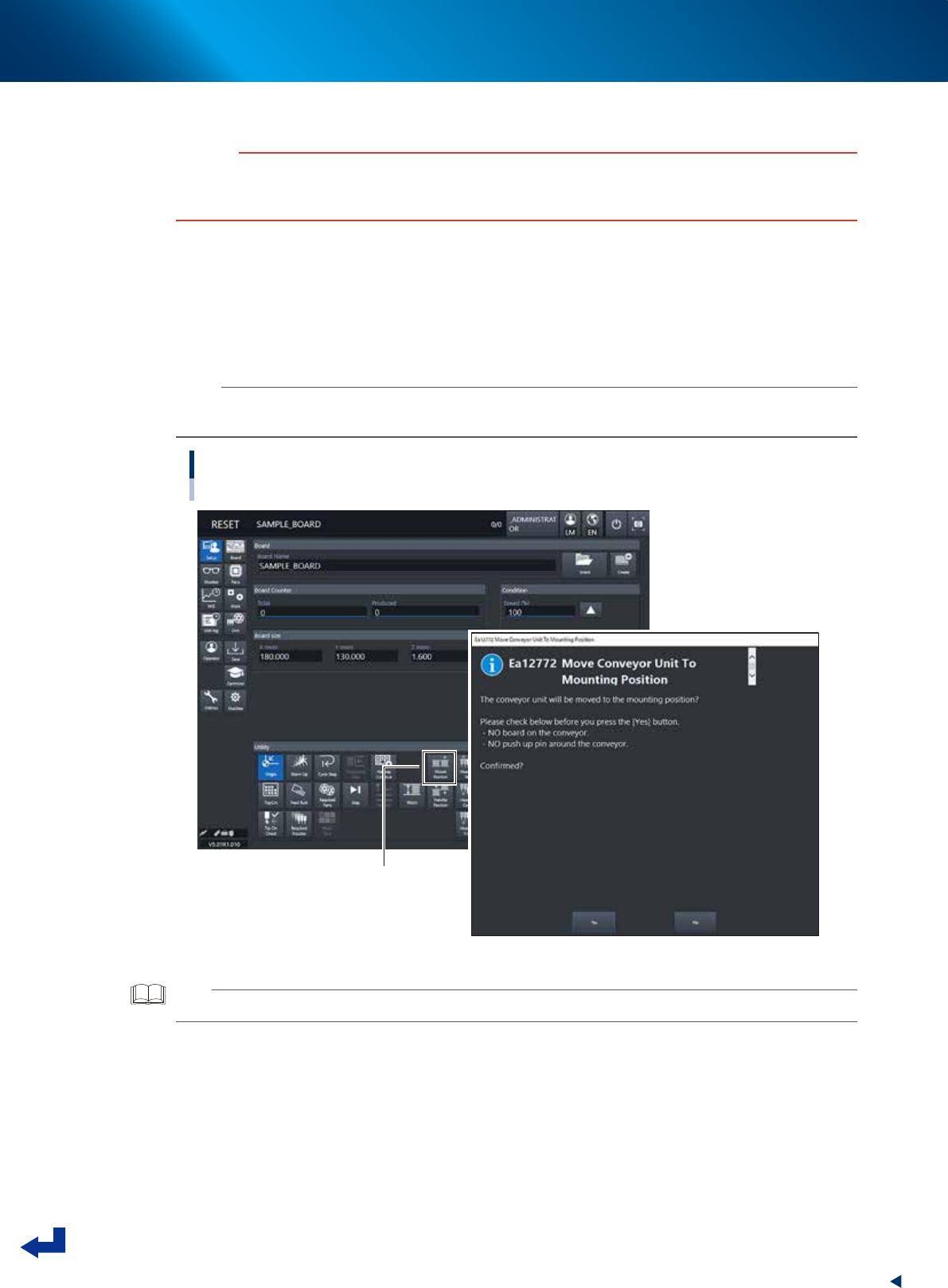
Move the conveyor to the mount position.
1. Press [Mount Position] button in [Setup] screen.
2. The message "Move Conveyor Unit To Mounting Position" is displayed, and then press the [Yes]
button.
The conveyor width changes to that specified in the board data, and then the mounting stage 2
moves to the mount position.
n
NOTE
When the board is of L=380mm or less, the mounting stage 2 moves to machine rear side.
Otherwise, the mounting stage does not move upon using the board of more than L=380mm.
Moving to the mount position
[MountPosition] button
24307-KMX-00
TIP
Pressing [Mount Position] also makes the conveyor width changed to the width specified in the board data.
1. Flow from starting up machine to production
3-12
Chapter 3 Flow from starting up machine to production
2
Lift the main stopper.
Lift the main stopper to place the board at the board mounting position.
Press the [Main Stopper] button on the “Unit” – “Conveyor” screen to lift the main stopper.
Press the [Main Stopper] buttons for both of stage 1 and stage 2 to lift the main stoppers.
Lifting the main stopper
[Unit] - [Conveyor] screen
[Main Stopper] button
24308-KMX-00
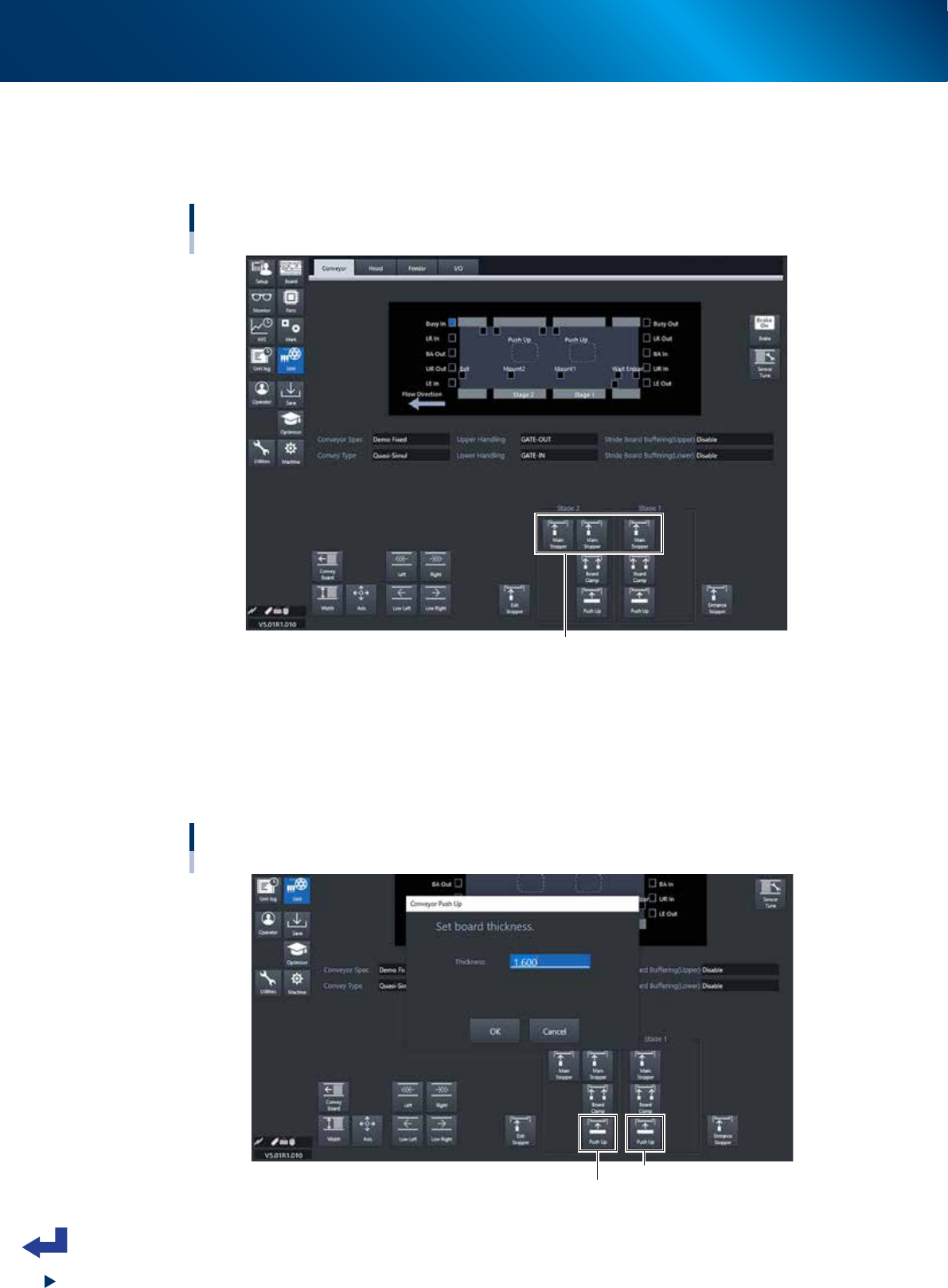
3
Move up the push-up plate.
1. Press [Push Up] button on [Unit] - [Conveyor] screen. Then "Conveyor Push Up" screen appears.
2. Press [OK] button after confirming the board thickness is correct. Then push-up plate moves up.
3. Move up the push-up plates for both stage 1 and stage 2 by following the procedure 1 and 2
above.
Moving up the push-up plate.
[Unit] - [Conveyor] screen
Stage 1 [Push Up] button
Stage 2 [Push Up] button
24309-KMX-00