YRM20_Ope_E.pdf - 第84页
5. Conveyor 1-53 Chapter 1 Unit names and functions 5. Conveyor 5.1 Conveyor unit T he following describes the con vey or unit that carries-in and clamps a board. Conveyor unit Right-to-left flow example 1 2 3 4 6 7 9 Bo…
4. Component supply section
1-52
Chapter 1 Unit names and functions
5
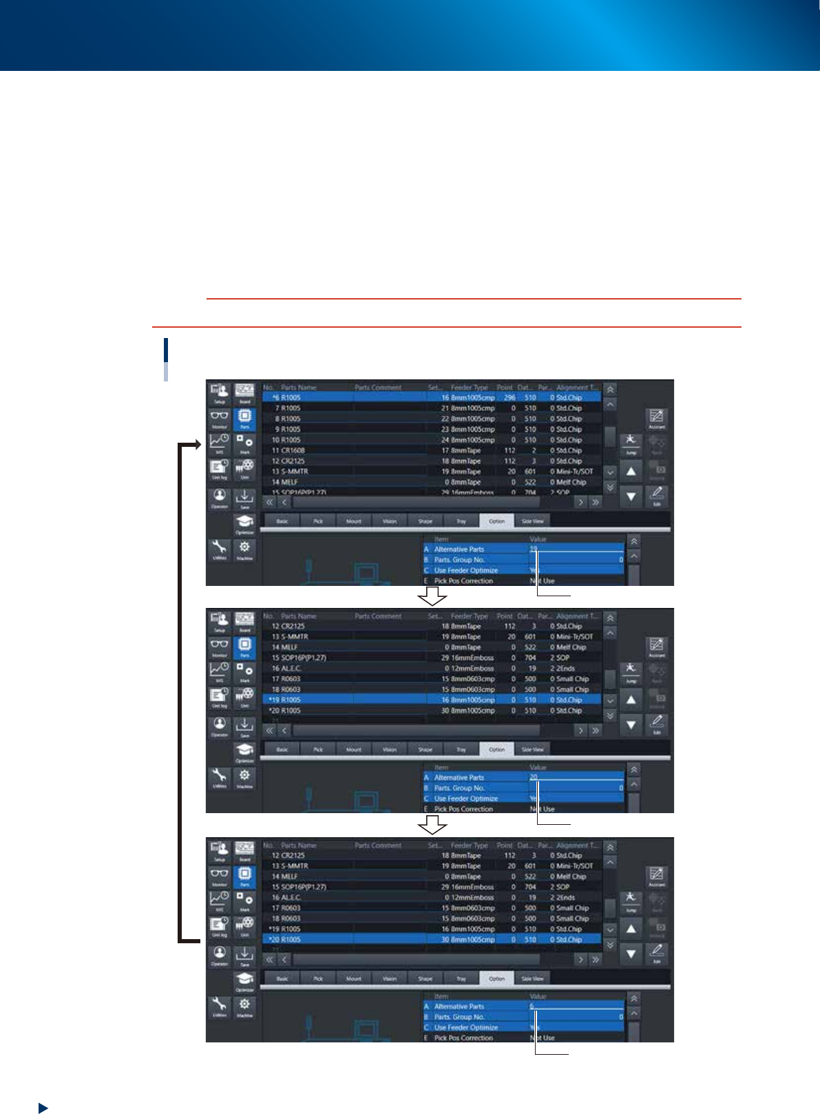
Specify the alternative component numbers.
1. Select the "Option" tab.
2. Select data No. 6 and enter "19" for the "A Alternative Parts" of Option tab.
3. Select data No.19 and enter "20"for the "A Alternative Parts" of Option tab.
4. Select data No. 20 and enter "6" for the "A Alternative Parts" of Option tab.
The settings above mean that the alternative component for No. 6 is No.19, that for No.19 is No.
20 and that for No. 20 is No. 6, just like making a loop as an alternative component group.
Detach No. 6 feeder from machine while it is substituted by No. 19, set new components and attach
again the reloaded feeder to No. 6 position of machine. When the reloaded feeder is set to No. 6,
components are supplied from feeder No. 6 automatically.
c
CAUTION
Data No. for alternative components must make a loop.
Alternative component number settings
Enter “19”.
Enter “20”.
Enter “6”.
24117-KMX-00
5. Conveyor
1-53
Chapter 1 Unit names and functions
5. Conveyor
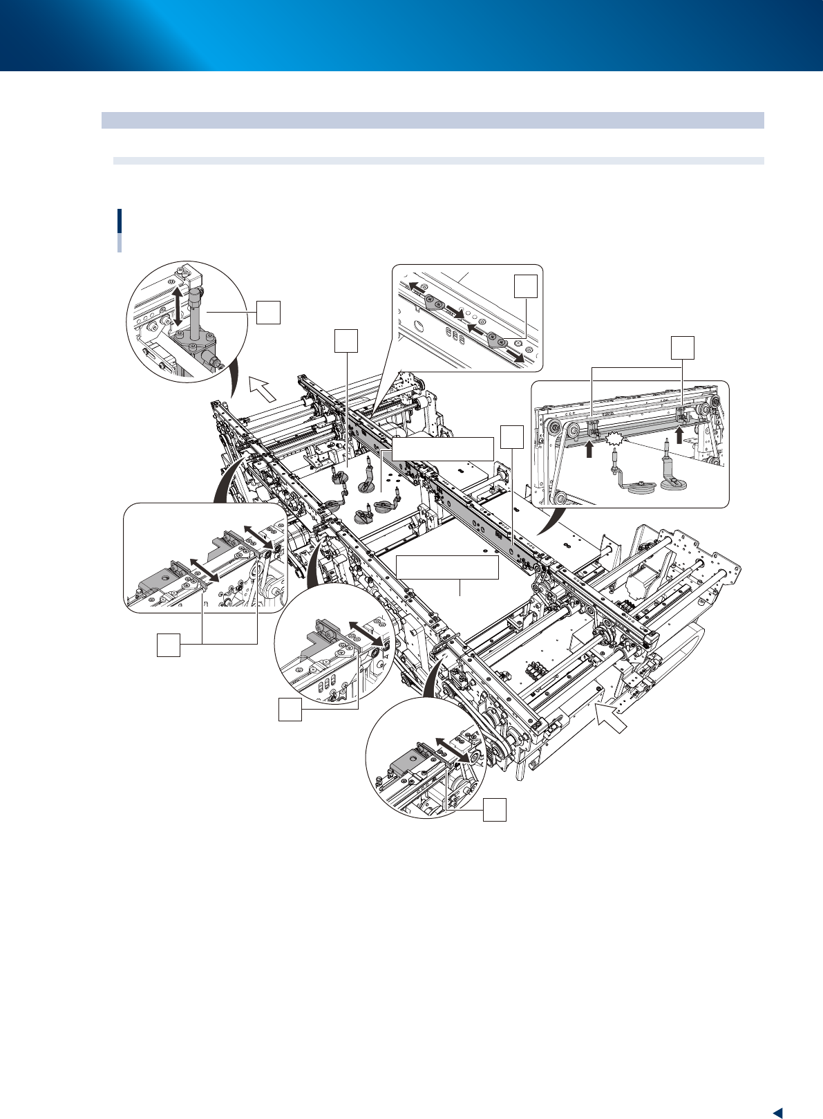
5.1
Conveyor unit
The following describes the conveyor unit that carries-in and clamps a board.
Conveyor unit
Right-to-left flow example
1
2
3
4
6
7
9
Board transfer direction
8
5 (Mounting stage 2)
5 (Mounting stage 1)
23132-KMX-00
1. Entrance stopper
If a board is on the mounting position already, other board carried into the conveyor waits at the
position of the entrance stopper.
2. Mounting stage 1 main stopper
The board stopper for the mounting position of the mounting stage 1. A board carried into the conveyor
is in contact with the main stopper, then it stops.
3. Mounting stage 2 main stopper
The board stoppers for mounting position of the mounting stage 2. There are two main stoppers for the
mounting stage 2, which are used depending on the board sizes.

5. Conveyor
1-54
Chapter 1 Unit names and functions
4. Exit stopper
When the machine in downstream doesn't demand a board, the mounted board waits at the position of
the exit stopper.
5. Push-up plate
6. Push-up pins
Push-up pins are arranged on the push-up plate depending on the spec and shape of board to be
mounted. When a board comes to the mounting position, the push-up plate raises and the push-up pins
secure the board by pushing it up from the bottom.
7. Board hold plate
8. Board clamp plate (clamp board assembly)
When a board comes to the mounting position, also the board clamp plate raises.
This clamps the board by pushing its edges up against the board hold plates.
The position of board hold plate varies depending on spec and shape of a board.
9. Pin push-up prevention sensor
This sensor stops the push-up plate raising motion by detecting the push-up pin pushing up the conveyor
frame, even when a push-up pins are placed between the push-up plate and the conveyor frame.
n
NOTE
YRM20 is specified only for the dual stage model above.
The whole mounting stage 2 of conveyor unit of dual stage machine moves back and forth (U-axis).
The mounting time can be shortened by the above motion as the mounting position, component pick-up position and head
unit come close each other.