YRM20_Ope_E.pdf - 第144页
4. Preparing component tape 2-47 Chapter 2 Basic o pera tion 4. Preparing component tape 4.1 T ape feeders 4.1.1 Setting component tape on the feeder T aking up ZSR feeder and 12mm ZS feeder as examples, this section des…
3. Displaying the production monitors
2-46
Chapter 2 Basic operation
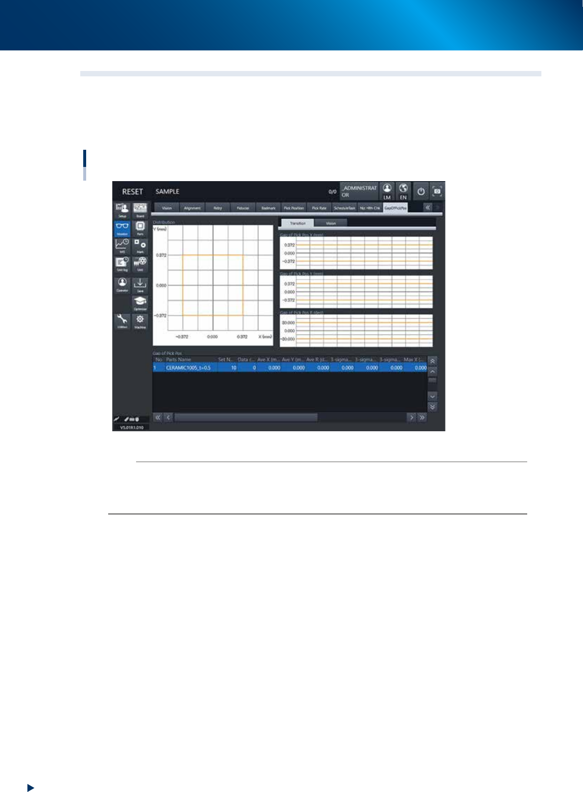
3.12 Gap of pick-up position
Displays the gap between the component center calculated by component recognition and the center of
camera field angle, for each component specified in board data, in graph form.
The re-examining of pick-up position or pick-up nozzle may be required for the component with large value
variability or biased recognition results in this graph.
Monitor: GapOfPickPos (Gap of pick-up position)
24225-KMX-00
n
NOTE
The displayed threshold of the gap of pick-up position amount can be specify to any value by selecting "Set" from [Parts]
- [Option] - [Pick Pos Check].
When [Normal] is selected for [Pick Pos Check], one-third of an opposite side of part size XY is specified automatically as
threshold of the gap of pick-up position amount.
4. Preparing component tape
2-47
Chapter 2 Basic operation
4. Preparing component tape
4.1 Tape feeders
4.1.1 Setting component tape on the feeder
Taking up ZSR feeder and 12mm ZS feeder as examples, this section describes how to set component tape
on the feeder.
n
NOTE
The 4 types of tape feeder are provided and applicable for YRM20; ZSR feeder, ZS feeder, auto loading feeder, and SS
feeder. Though some limitation occur upon using SS feeder.
See "4.2 SS Feeder" for details.
c
CAUTION
Always use a temporary tape set station or a power station for the off-line setup to set the tape. Make sure to prevent
essentially to set tape on tape feeder on feeder exchange carriage already attached to mounter, as a component tape may
fall inside of mounter upon working.
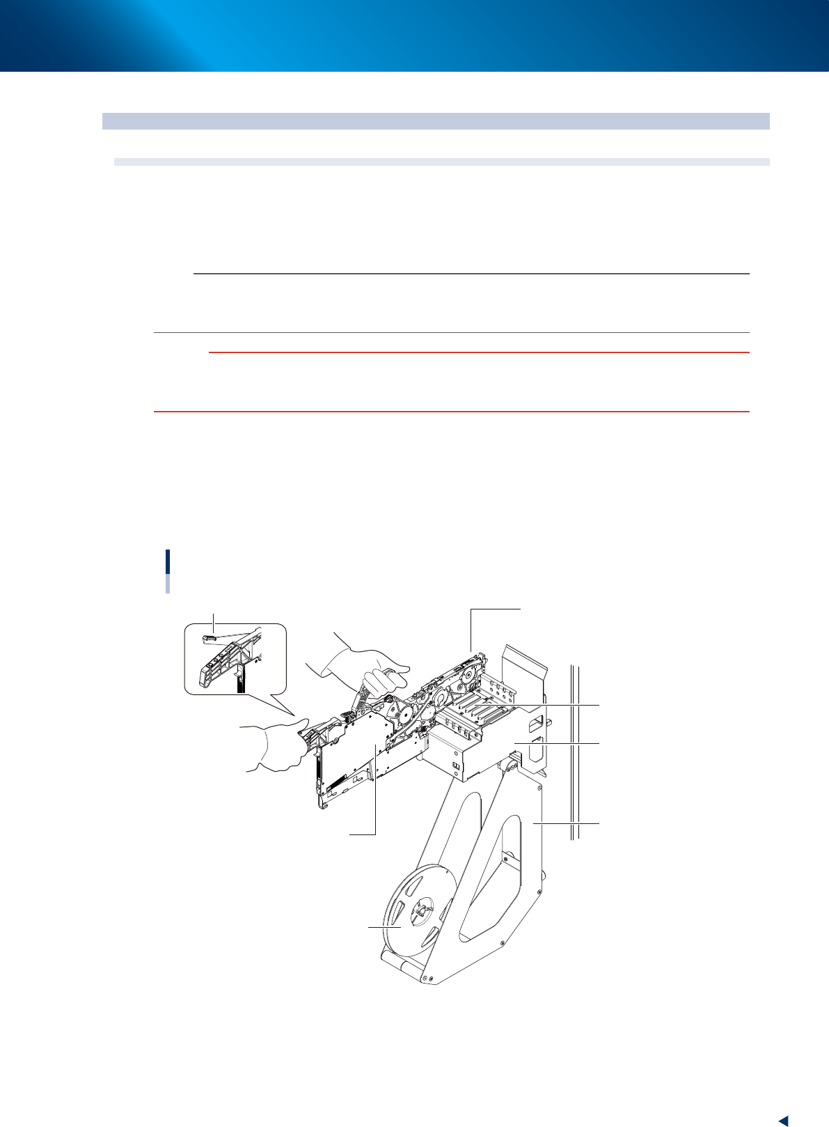
1
Set the feeder and tape reel on the temporary tape set station.
1. Place the feeder in the temporary tape set station or power station for the off-line setup.
While keeping gripping the unclamping lever of the feeder, set it to the leftmost set position (the
point where the feeder connector is located) by running the feeder along the feeder guide rail
of temporary tape set station.
2. Set the tape reel for operation to the reel holder of the temporary tape set station.
Setting the feeder
Set to the leftmost position.
Feeder
Feeder guide rail
Unclamp lever
Temporary tape set
station
Reel holder
Reel
23202-KMX-00
4. Preparing component tape
2-48
Chapter 2 Basic operation
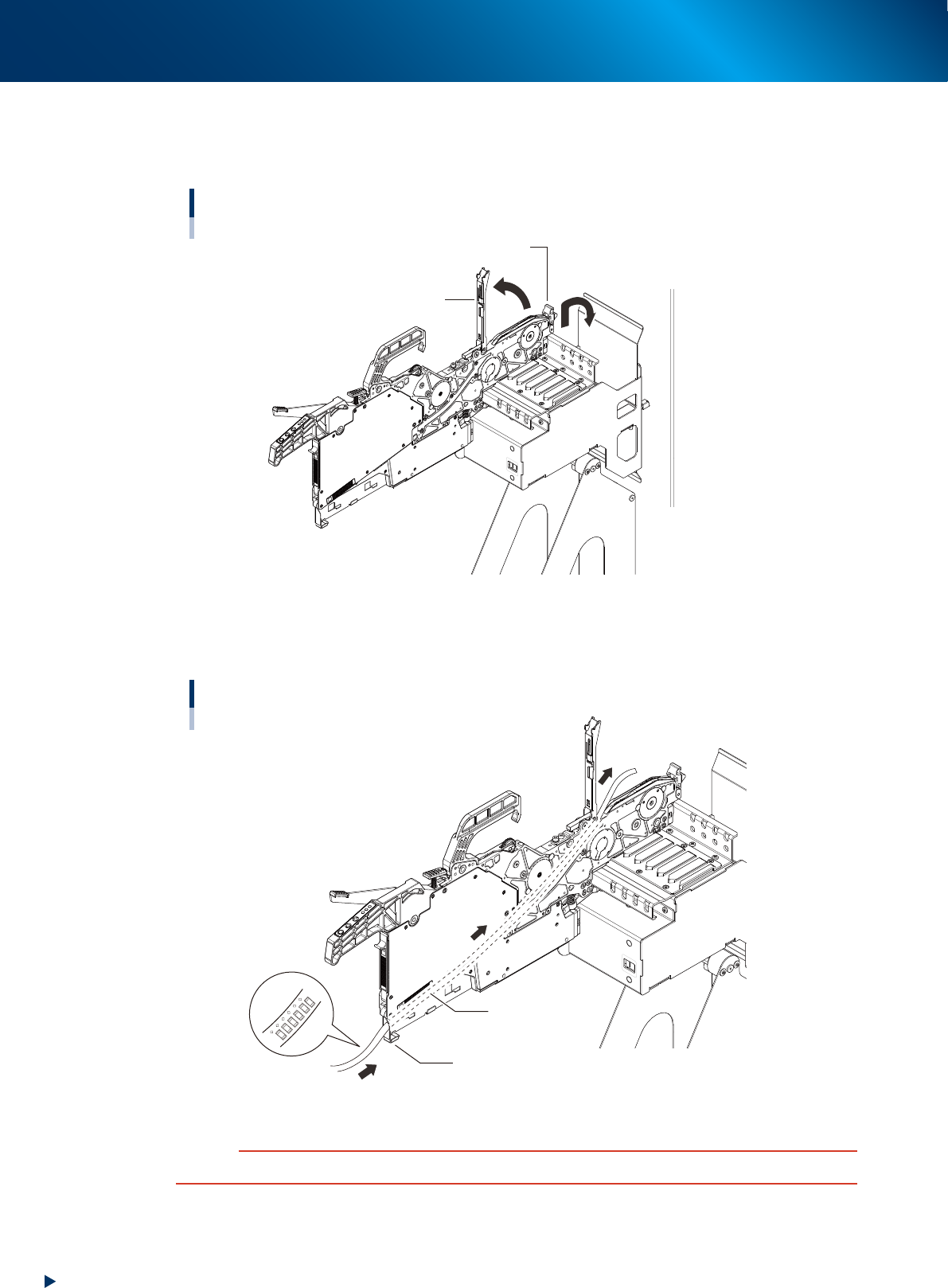
2
Lift up the tape guide assembly.
1. Lay down the tape guide front lever while lifting it up.
2. Raise the tape guide assembly.
Raising the tape guide assembly
Tape guide assembly
Tape guide front lever
23203-KMX-00
3
Set the tape in the tape feeder.
Run the component tape through the component tape insertion slot at the rear part of feeder.
Setting the tape
Component tape insertion slot
Tape
Be sure face the tape
top/bottom.
23204-KMX-00
c
CAUTION
Be sure to face the tape top/bottom correctly.