YRM20_Ope_E.pdf - 第202页
1. Flow from starting up machine to production 3-22 Chapter 3 Flow from starting up machine to production 1.8 Confirming nozzles Confirm the nozzles before starting the production. This procedure description in this sect…
1. Flow from starting up machine to production
3-21
Chapter 3 Flow from starting up machine to production
1.7 Preparing component tape (Tape feeder)
When the conveyor gets ready for operation, prepare the component tape. This procedure description in this
section assumes that the board data to be used for production has been read out.
1
Open the “Required Parts” screen.
Press the [Required Parts] button and the “Required Parts” screen appears.
2
Set the feeders loaded with component tape.
The “Required Parts” screen lists the “Set Num.”, “Parts Name”, “Parts No.” and other parameters.
While observing this list, attach the feeders loaded with component tape in each corresponding
feeder set location, or attach the feeder exchange carriage to which the feeders are set, to machine.
n
NOTE
See chapter 2,"4. Preparing component tape" for the procedure to set component tape into the feeder and attach the
feeder to main machine.
n
NOTE
The component set positions (Set Num.) F1 through F64 are of the feeder exchange carriage at front side, and the F101
through F164 of the feeder exchange carriage at rear side.
P1 to P30 are the pallet numbers for the tray component supply unit at front side, P101 to P130 are the pallet numbers for
the tray component supply unit at rear side.
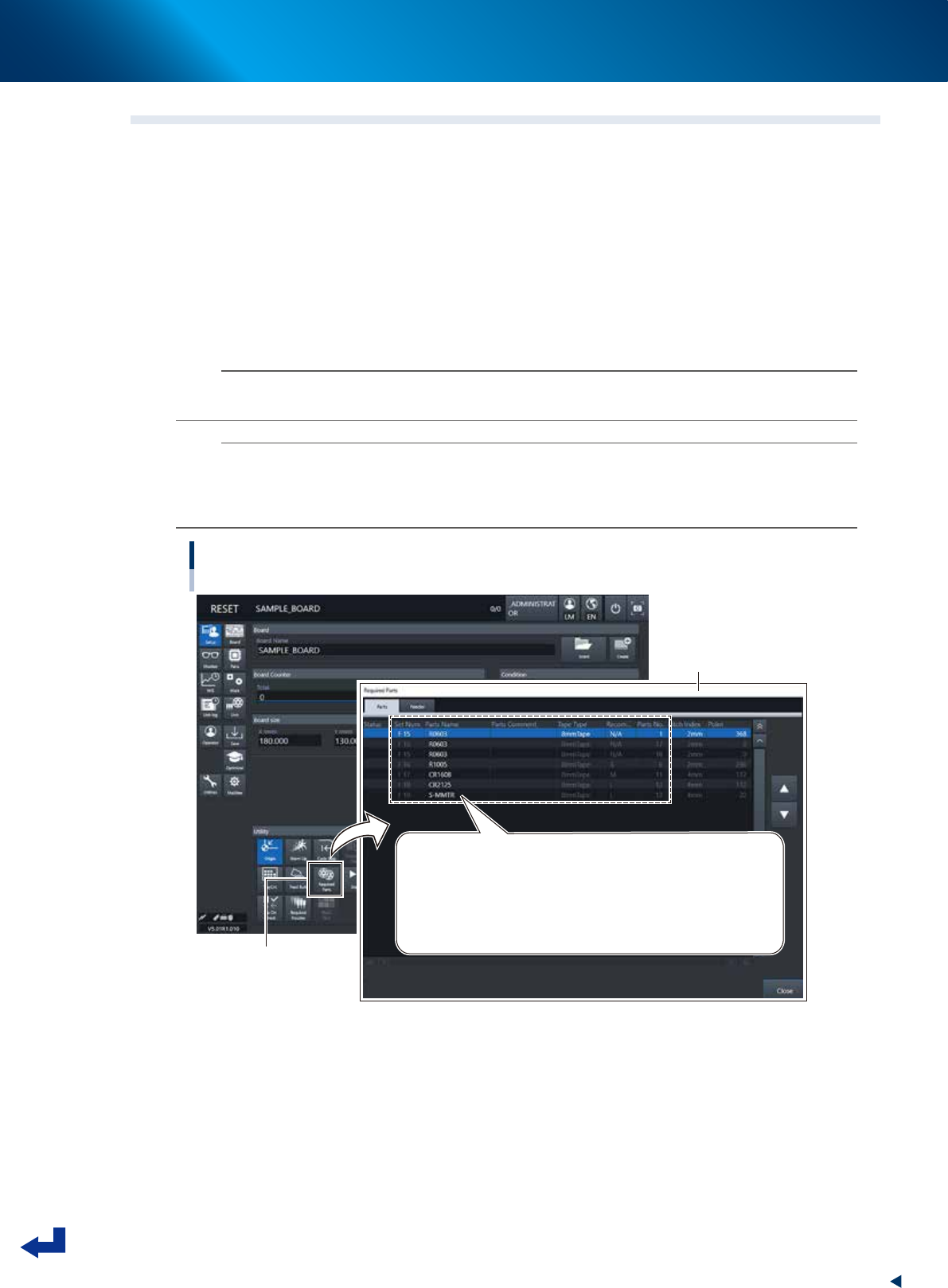
Preparing component tape
[Setup] screen - “Required Parts” screen
[Required Parts] button
“Required Parts” screen
Set Num. / Parts Name / Tape Type / Parts No. and other parameters appear.
Set Num. : F1 to F64 are set in the front feeder exchange carriage
F101 to F164 are set in the rear feeder exchange carriage
P1 to P30 are set in the front tray component supply unit
P101 to P130 are set in the rear tray component supply unit
24312-KMX-00
1. Flow from starting up machine to production
3-22
Chapter 3 Flow from starting up machine to production
1.8 Confirming nozzles
Confirm the nozzles before starting the production. This procedure description in this section assumes that
the board data to be used for production has been read out. Note that Steps 1 and 2 are not necessary where
the setting is such that all the heads go through the automatic nozzle changing process.
1
Open the “Required Nozzles” screen.
Press the [Required Nozzles] button on the “Setup” screen, then the “Required Nozzles” screen
appears.
2
Confirm the nozzle types.
If the machine is not equipped with the nozzle station or the machine has a head that does not go
through the automatic nozzle changing process, the types of nozzles appear on the “Nozzle Type”
list. Confirm that these nozzles in the list match the nozzles that are currently attached on the heads.
Note that this process is not necessary if set to “AUTO”.
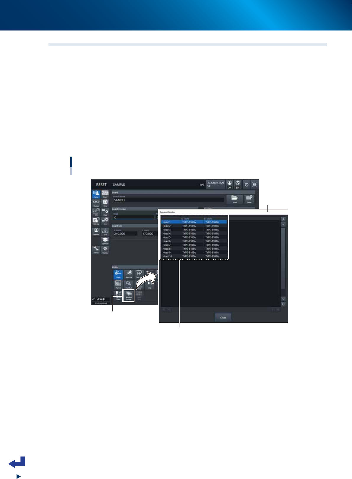
Confirming the nozzle types
[Setup] screen - “Required Nozzles” screen
[Required Nozzles] button
Confirm that these nozzles in the list match the nozzles
that are currently attached on the heads.
* This process can be skipped if set to “AUTO”.
“Required Nozzles”
screen
24313-KMX-00
1. Flow from starting up machine to production
3-23
Chapter 3 Flow from starting up machine to production
3
Open the “CHECK NOZZLES” screen.
Press the [Tip Cln Check] button on the “Setup” screen, then the “CHECK NOZZLES” screen appears.
4
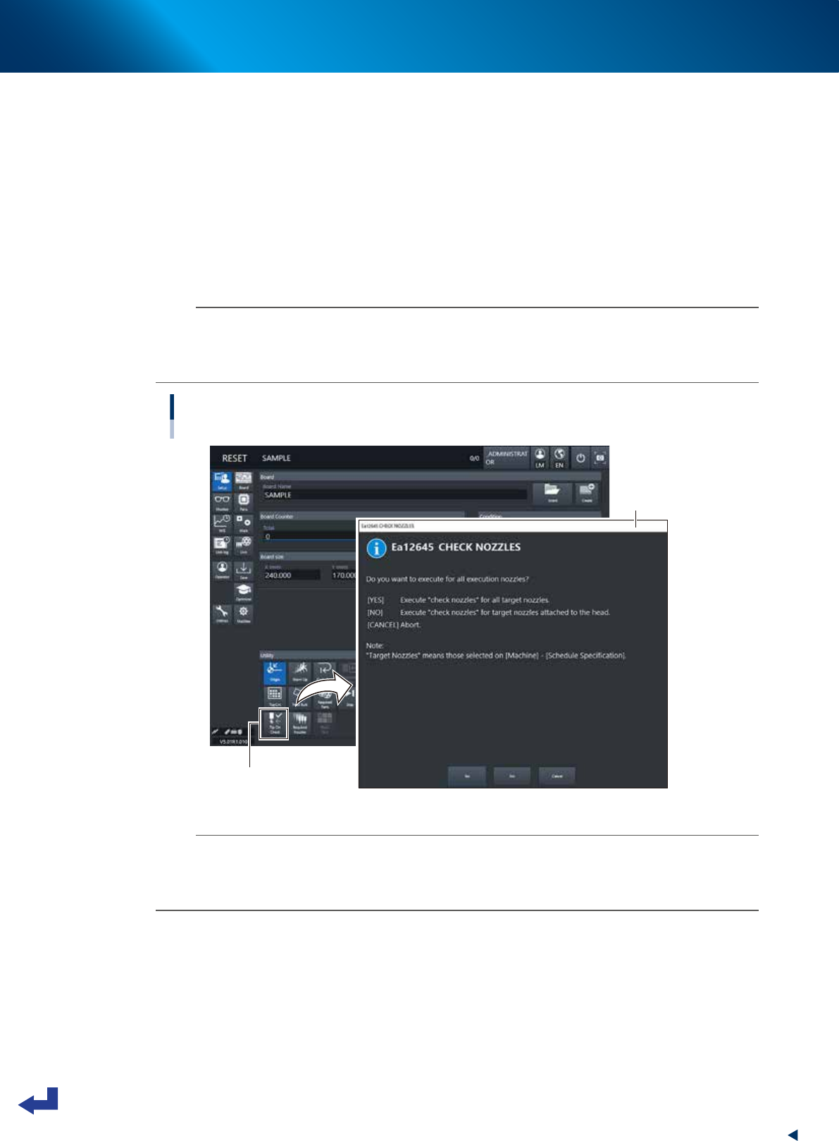
Check the cleanness on the nozzle tips.
Check the contents on the “CHECK NOZZLES” screen and then select any of the following buttons.
[Yes] : Automatic nozzle change process takes place to confirm all the object nozzles to be
checked.
[No] : Of the nozzles currently attached to the heads, only the nozzles to be checked are
confirmed.
[Cancel] : Cancel the operation.
n
NOTE
The “Nozzle Tip Cleanness Check” is a function that the camera views the nozzle tips without components to judge the
nozzle cleanness. Since the camera recognizes the reflection of light coming from solder deposited around the nozzle tips,
the camera works for small tip nozzles such as 8103A, 8104A, 8105A, 8106A, 8107A, 8108A, 8004H, 8006H and
the like.
]
Nozzle Tip Cleanness Check
[Setup] - “CHECK NOZZLES” screen
[Tip Cln Check] button
“CHECK NOZZLES”
screen
24314-KMX-00
n
NOTE
• The “Nozzle Tip Cleanness Check” is available if it is specified on the "Machine setting".
• Since dirt deposits gradually, the check may turn out to be OK or NG if checking a few times at the initial stage of
accumulating dirt.
• It is recommended to clean the nozzles periodically. See the maintenance manual, chapter 3, "1.2 Nozzle cleaning".