YSP_Users_E.pdf - 第112页
4-9 4 Creating and setting the data V: Alignment Select the processing method after fiducial mark recognition. Set to "UseAlign" in normal operation, and the machine immediately stops when a mark recognition er…
4-8
4
Creating and setting the data
Board parameters (2)
64411-L3-10
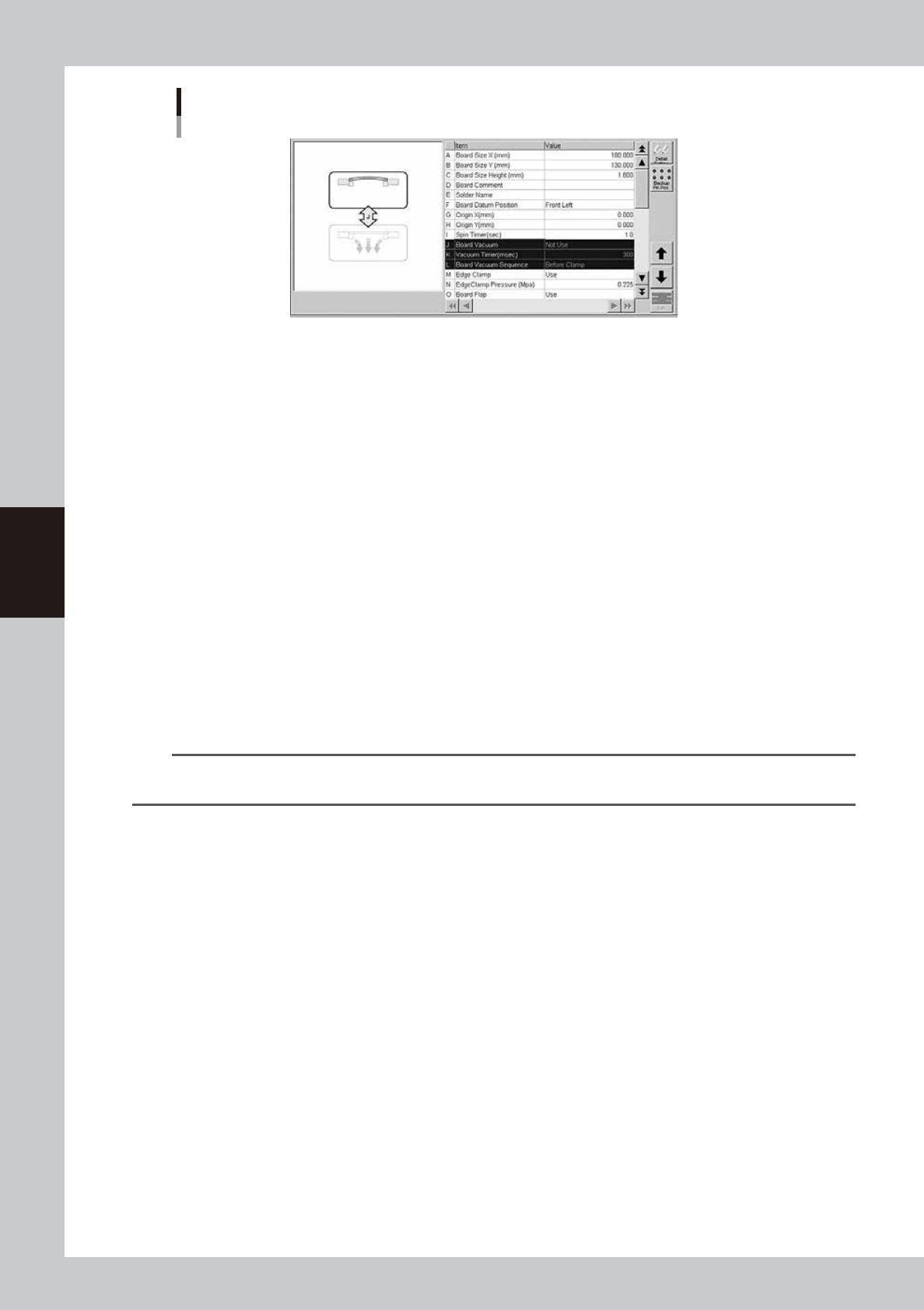
J: Board Vacuum
This parameter is enabled only for machines equipped with an optional vacuum gripper. Set to "NotUse" in most cases.
When curved boards or thin boards are to be printed, setting this parameter to "Use" actuates the vacuum gripper to fix
the board from the backside. When this parameter is set to "Use", also specify an appropriate time (msec) in the "Vacuum
Timer" and "Board Vacuum Sequence" parameters.
K: Vacuum Timer (msec)
When the "Board Vacuum" parameter is set to "Use", set the timer (msec) here to initiate the next action after the push-up
plate has moved up. This parameter is enabled only for machines equipped with an optional vacuum gripper.
L: Board Vacuum Sequence
This parameter is enabled only when the "Board Vacuum" parameter is set to "Use". Set to "Before Clamp" to turn on the
vacuum gripper before clamping a board. Set to "After Clamp" to turn on the vacuum gripper after clamping a board.
M: Edge clamp
The edge clamps secure the board in the printing position by laterally pushing on the board edge. Set this parameter to
"Use" in most cases. If printing on boards which cannot be clamped from the edge such as thin ceramic boards, set to
"NotUse" and use a vacuum board gripper instead.
N: Edge Clamp Pressure
Set an edge clamp pressure level (0.05 to 0.225MPa) that is optimal for the board. This pressure is set to 0.225MPa as the
default.
If multi-block boards or thin boards warp upwards when force is applied by the edge clamp, reduce the edge clamp air
pressure. Conversely, increase the air pressure if you want to clamp heavy boards more securely.
n
NOTE
When data (edge clamp pressure: 0.4MPa) set by the YGP (earlier model) is loaded, it is automatically be converted
to 0.225MPa in the YSP.
O: Board flap
Set whether to use the board flap that presses on the board edge from above.
Usually, set this parameter to "Use". Using the board flap corrects the upward warp of a board that might occur when
clamped.
Q: Board Press (option)
The board press unit holds down the board surface to correct the overall warp. Set this parameter to "Use" when using
the board press unit (option) or to "NotUse" when not using that unit. (This parameter is available only for machines
equipped with an optional board press unit.)
R: Press Timer (msec)
When an optional board press unit is used, set the length of time to press on a board.
S: Board Press Sequence
When an optional board press unit is used, set whether to start pressing on a board before or after the edge clamp is
actuated.
T: Push Up Speed (%)
Specify the ascent/descent speeds for the push-up plate in percentage. Setting to "100" is acceptable in most cases, but
reduce it if you want to lessen the impact when the push-up jigs or pins move up against the board.
U: Print Execution
Select the operation mode from "Exec" or "Skip".
Exec : The machine performs solder printing.
Skip : The machine operates without applying any force.
4-9
4
Creating and setting the data
V: Alignment
Select the processing method after fiducial mark recognition. Set to "UseAlign" in normal operation, and the machine
immediately stops when a mark recognition error occurs. When this is set to "IgnoreErr", the machine continues operation
even if a mark recognition error occurs.
W: Print Feedback
Always set this parameter to "Use" when producing boards. (If you want to check the squeegee head movement without
controlling the printing pressure, set this parameter to "NotUse".
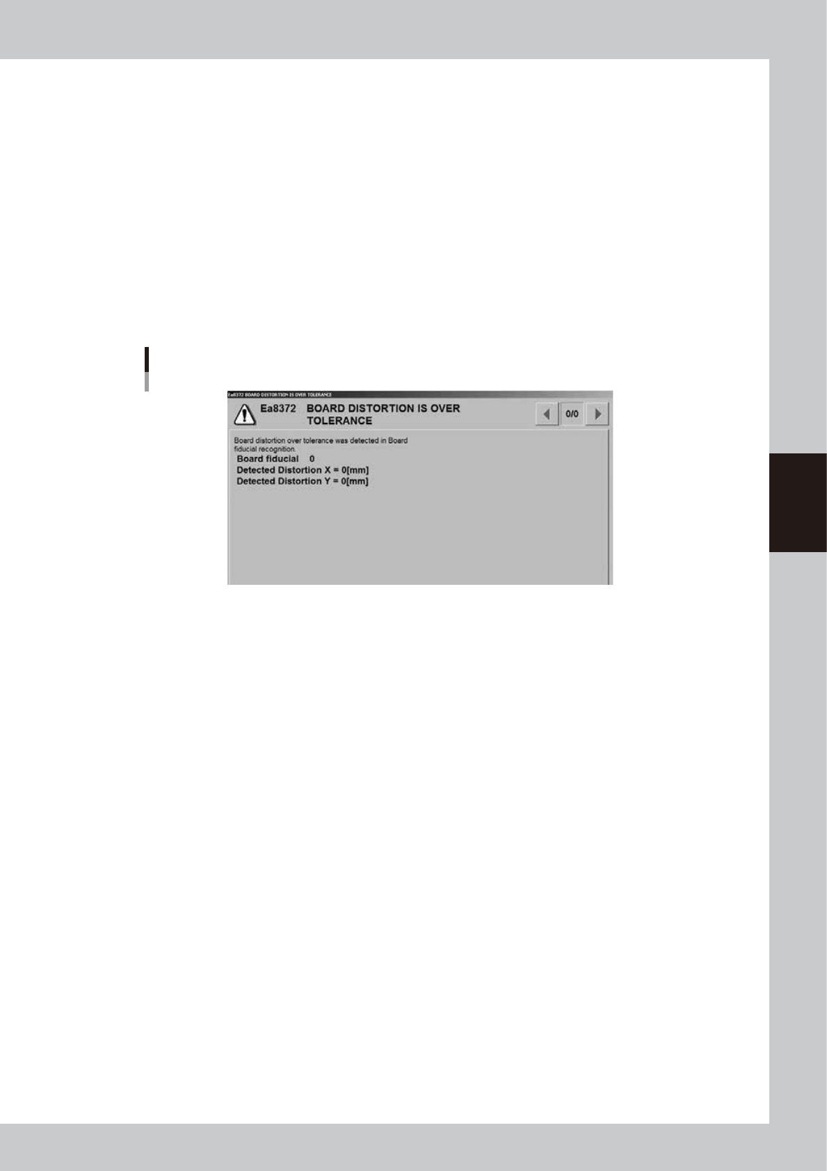
X: Board Distortion Tol.
This parameter specifies the allowable distortion limit when checking the distortion component in the board fiducial
recognition position and local fiducial mark recognition positions on the board. The distortion check is not performed
when this parameter is set to "0.00".
If the distortion component calculated by recognizing the board fiducial marks or local fiducial marks during automatic
operation exceeds the allowable limit specified here, an error message box appears as shown below and the machine
stops. After closing the error message box, you can select whether to print solder on the board or to convey the board
out without printing solder according to the dialog box that appears.
Error message for board distortion
64412-L3-00
Y: Air conditioner interlock
When an optional temperature control unit is used, set whether or not to enable the interlock mechanism that functions
if an abnormal temperature is detected.
4-10
4
Creating and setting the data
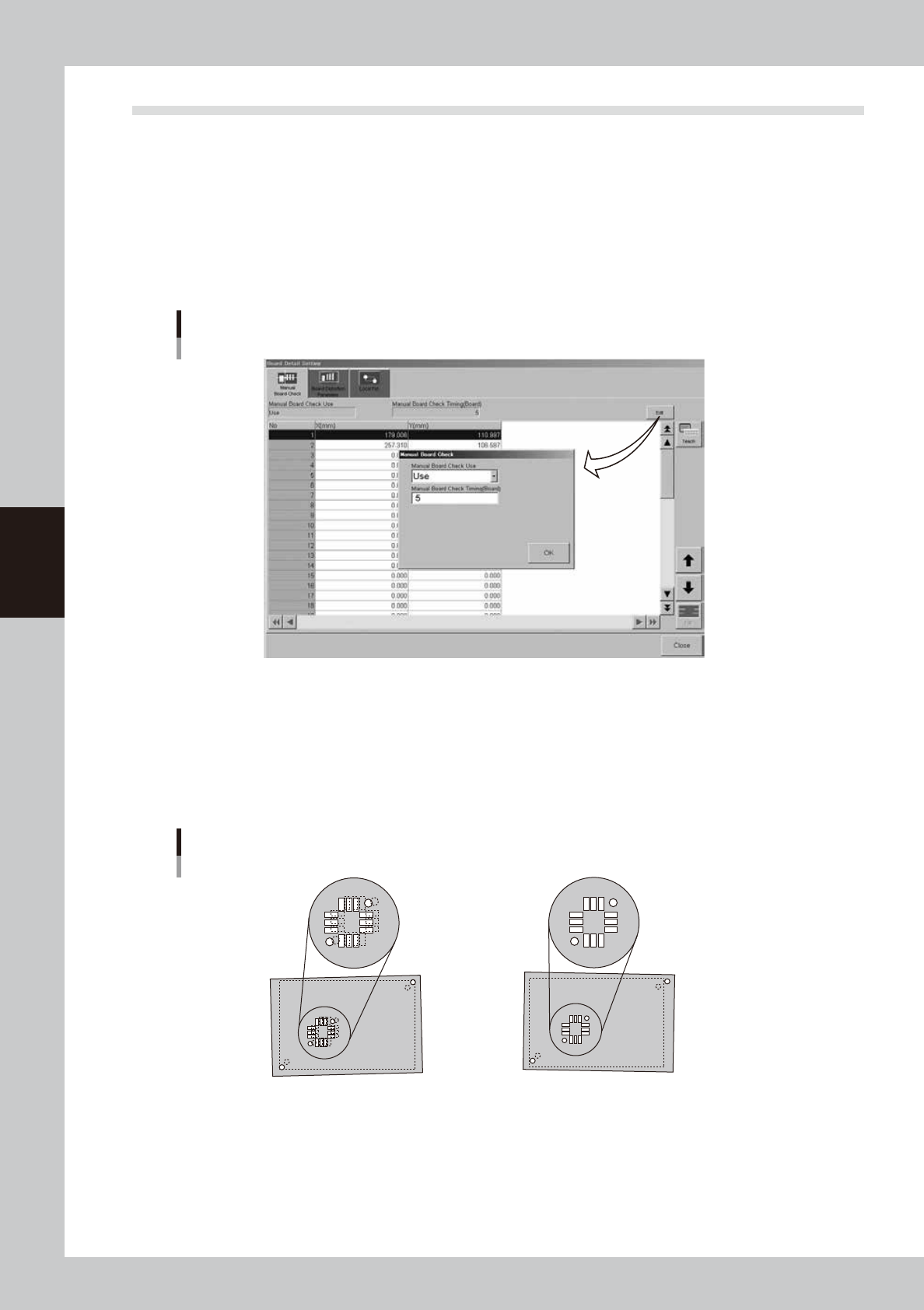
3.2 Board data detail setting
When you press the [Detail] button on the [Print]-[Board] tab, a dialog box with the [Manual Board Check],
[Board Distortion Parameter] and [Local Fid.] tabs appears. You can set the board check positions, board
distortion offset parameters and local fiducial function here. Setting methods are explained below.
l
Board check positions
On the [Manual Board Check] tab, you can specify the positions on the board where you want to make a visual check of
printed solder. (Refer to "9. Making a test print" in this chapter for solder-print testing.) Pressing the [Edit] button at the
upper right opens the "Manual Board Check" dialog box. Set whether to use this function or not, as well as the board
interval to make a visual check.
[Manual Board Check] tab
64413-L3-10
l
Board distortion offset *Print inspection function (option)
When boards in the same lot tend to be elongated or distorted in the same direction, or the same problem appears only
in the board fiducial positions, then overall position deviations might occur in the solder-print inspection. These
deviations can occur regardless of whether print accuracy was maintained by visual alignment. If this happens, use the
board distortion offset function to add correction offsets to the overall inspection coordinates to get the correct position
using solder-print inspection results (solder position) of the printed board used as the reference.
Board distortion offset
1. When the board fiducial positions have
elongation or distortion, the board clamping
deviation cannot be corrected, and overall
position deviations will occur in the
solder-print inspection results.
2.
Solder accurately printed on the land patterns
is recognized by the vision camera and the
position offset data is used as feedback.
(overall shift)
63406-L3-00