YSP_Users_E.pdf - 第150页
4-47 4 Creating and setting the data 9 Check the result of the gr aphic alignment. Press the [T race] button to check if the coordinates alignment result is corr ect. 0 Remo ve the board from the conve yor . Press the [C…
4-46
4
Creating and setting the data
5
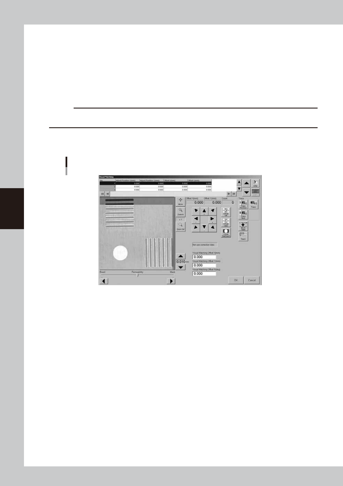
Press the [Visual Matching] button.
If a position offset (deviation) is found by graphic or visual alignment, you can adjust it in the "Visual
Matching" screen that appears when you press the [Visual Matching] button. (Skip this step when no
position offset is found.)
1. While moving the image in the XY directions using the [Arrow] buttons, make fine-alignments until
position offsets are no longer seen. The values in the "Offset X" and "Offset Y" boxes just above the
[Arrow] buttons change as you move the image.
2. After aligning the position, press the [Offset Set] button.
The number "1" appears in the "Count" box, then next alignment coordinates is displayed.
c
CAUTION
Even if there are no position offset, press (Offset set) button. The correct offset can't be calculated without pressing
(Offset set) button for each alignment coordinates.
3. Repeat the procedure above to set the offset for 2nd to 4th point, too..
The number in the "Count" box increments each time an alignment is made ([Offset Set] button is
pressed).
"Visual Matching" screen
64446-L3-00
6
When graphic alignment completed, press the [Offset Total Teach] button.
The offset amount for the entire board is then calculated based on the adjusted offset values and the
results displayed in the "Visual Matching Offset X", "Visual Matching Offset Y" and "Visual Matching Offset
R" boxes in the lower part of the screen.
Press the [Offset Clear] button if you want to clear the offset amount and retry from the beginning.
7
Press the [OK] button to update the offset amount.
The offset amount calculated here will be entered in the "F. Mask Offset XYR" and "B. Mask Offset XYR" in
the squeegee data. If you do not want to update the offset amount, press the [Cancel] button.
8
Graphic alignment for the specified position.
If the printing position needs to be aligned on the specified position, adjust the center and the R
deviation and update the offset before graphic alignment.
1. Press the [Visual matching] button to enter [Visual matching] screen. Select the coordinates to be
aligned and press the [Trace] button.
2. Align the image with the [Arrow] buttons, then press the [Offset set] button.
3. Press the [Offset Total Teach] button, then press the [OK] button to close the window.

4-47
4
Creating and setting the data
9
Check the result of the graphic alignment.
Press the [Trace] button to check if the coordinates alignment result is correct.
0
Remove the board from the conveyor.
Press the [Close] button to close the [Visual alignment] screen. Then press the [Convey Out] button to
remove the board.
4-48
4
Creating and setting the data
9. Making a test print
When visual alignment on the created data has been made, make a test print before starting board
production, to check the printing conditions and accuracy and make necessary adjustments. In test print, we
recommend covering the board with a transparent sheet (option) to protect the board just as with the rolling
operation.
n
Note
When printing with newly created board data, always make a test print before starting production to check the
printing conditions and accuracy. Even when printing with board data you have used, we recommend making a test
print before beginning daily work.
1
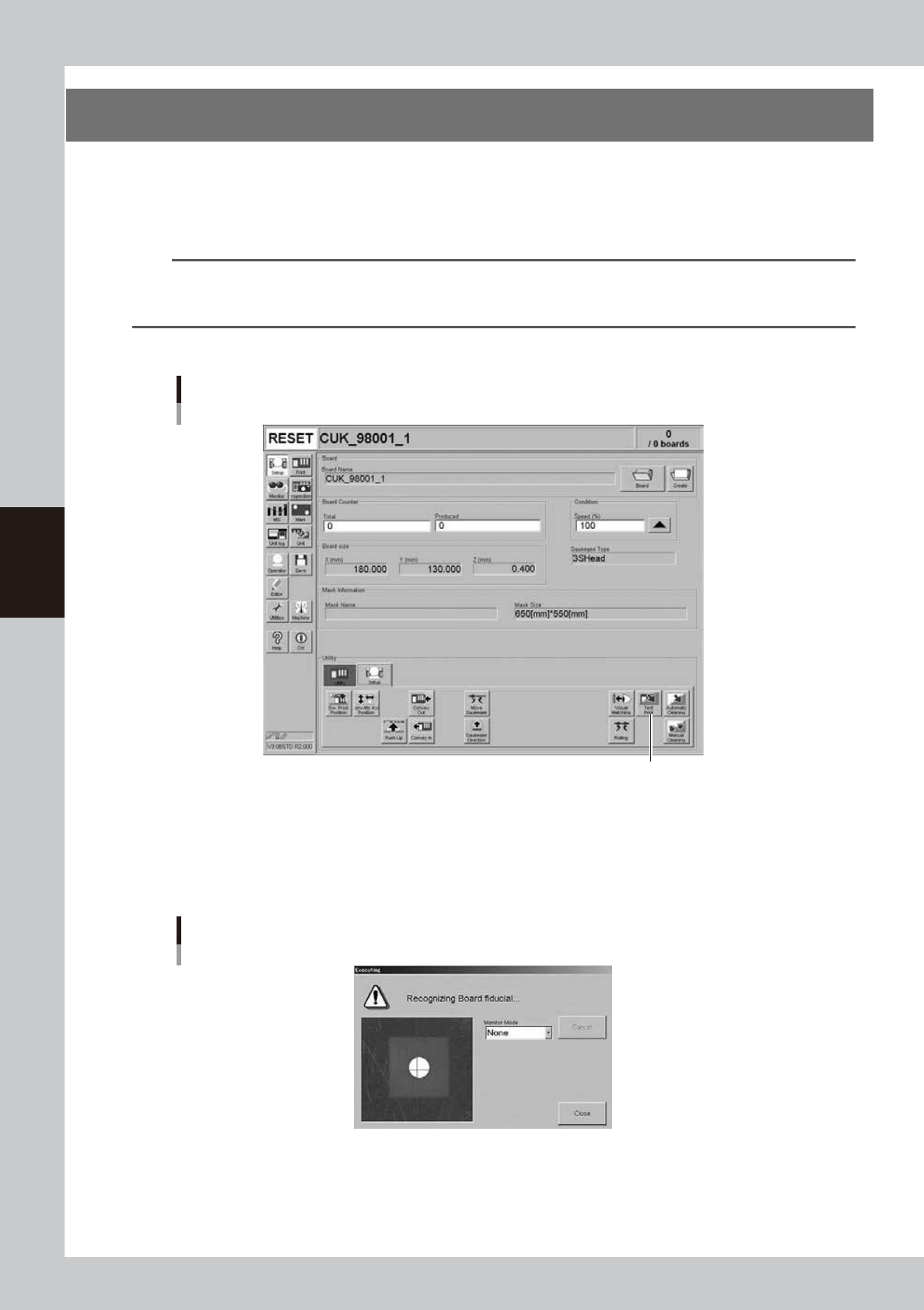
Press the [Test Print] button on the Setup screen.
[Test Print] button
[Test Print] button
64447-L3-00
2
Follow the message on the screen to load a board on the conveyor.
This step is skipped when a board has already been clamped on the conveyor.
When the board is clamped on the conveyor, the board fiducial mark and the mask fiducial mark are
automatically recognized. (The mark recognition process is skipped if not using the fiducial mark
function.)
Fiducial mark recognition screen
64448-L3-00