YSP_Users_E.pdf - 第114页
4-11 4 Creating and setting the data Board distortion offset parameter setting [Calculate Distortion] button 64414-L3-00 Pressing the [Calculate Distortion] button on the right of the [Board Distortion P arameter] tab sh…
4-10
4
Creating and setting the data
3.2 Board data detail setting
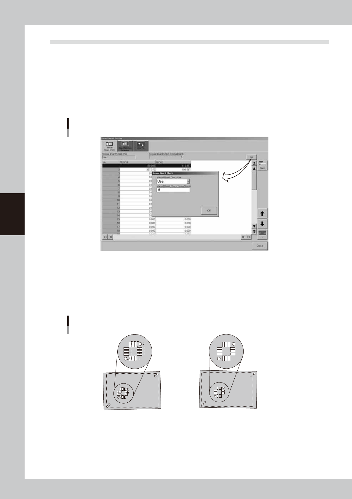
When you press the [Detail] button on the [Print]-[Board] tab, a dialog box with the [Manual Board Check],
[Board Distortion Parameter] and [Local Fid.] tabs appears. You can set the board check positions, board
distortion offset parameters and local fiducial function here. Setting methods are explained below.
l
Board check positions
On the [Manual Board Check] tab, you can specify the positions on the board where you want to make a visual check of
printed solder. (Refer to "9. Making a test print" in this chapter for solder-print testing.) Pressing the [Edit] button at the
upper right opens the "Manual Board Check" dialog box. Set whether to use this function or not, as well as the board
interval to make a visual check.
[Manual Board Check] tab
64413-L3-10
l
Board distortion offset *Print inspection function (option)
When boards in the same lot tend to be elongated or distorted in the same direction, or the same problem appears only
in the board fiducial positions, then overall position deviations might occur in the solder-print inspection. These
deviations can occur regardless of whether print accuracy was maintained by visual alignment. If this happens, use the
board distortion offset function to add correction offsets to the overall inspection coordinates to get the correct position
using solder-print inspection results (solder position) of the printed board used as the reference.
Board distortion offset
1. When the board fiducial positions have
elongation or distortion, the board clamping
deviation cannot be corrected, and overall
position deviations will occur in the
solder-print inspection results.
2.
Solder accurately printed on the land patterns
is recognized by the vision camera and the
position offset data is used as feedback.
(overall shift)
63406-L3-00
4-11
4
Creating and setting the data
Board distortion offset parameter setting
[Calculate Distortion]
button
64414-L3-00
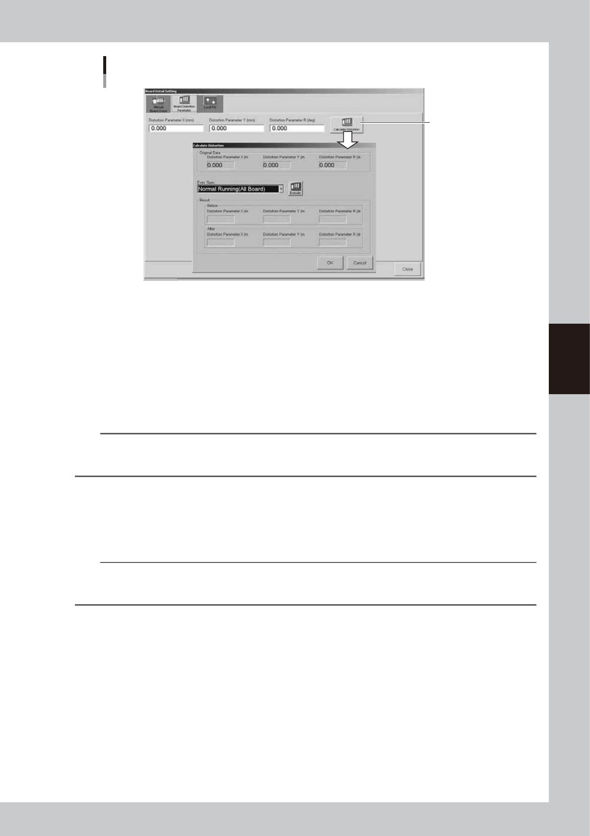
Pressing the [Calculate Distortion] button on the right of the [Board Distortion Parameter] tab shows the "Calculate
Distortion" dialog box. Inside this dialog box, the "Original Data" group box shows the original settings before
corrections were obtained.
Press the [Execute] button to run the solder-print inspection and detect the overall deviation in solder print positions. The
X, Y and R distortion corrections are then acquired automatically.
The "Results" group box shows corrections "Before" the current solder-print inspection. It also shows corrections (offsets)
newly acquired "After" the solder-print inspection. These "Before" and "After" correction values are compared and the
solder-print inspection repeated until these values no longer change. The solder-print inspection has to be run several
times (3 to 5 times) before this process is complete. Press the [OK] button to enable the corrections now obtained. Press
the [Cancel] button to discard these values.
n
NOTE
The solder-print inspection is run to acquire distortion values so solder-print inspection data must be created in
advance. As much objects to be inspected as possible should be entered in order to detect the correct print position
for the entire board. (For details, see "Print inspection function" in the separate Option Manual.)
l
Local fiducial function
Uniform printing accuracy at important points can be ensured by recognizing marks near positions where it is essential
to maintain good printing accuracy. This is especially true when printing on board within the same lot having elongation
or distortion irregularities. The [Local Fid.] tab allows you to set the type of mark and position coordinates of the local
fiducial marks being used.
TIP
Position correction with local fiducial marks is also used to calculate the print position, as well as calculate the printing
position for running the solder-print inspection on machines equipped with the solder-print inspection function
(option).
4-12
4
Creating and setting the data
Board fiducial and local fiducial functions
1. This function runs board
fiducial recognition and
calculates the amount of offset
for correcting the board
deviation that may occur when
clamped on the print table.
2. This function uses board fiducial
recognition results to correct the
board deviation that may occur
when clamped on the print table.
It then recognizes the marks at
the local fiducial positions that
were preregistered.
3. If there is no elongation or
distortion on the board then no
local fiducial recognition offset is
issued. But if elongation or
distortion is present, the local
fiducial recognition offset (only in
XY direction) is added unchanged,
to the board fiducial offset.
Board fiducial function
Board fiducial function
Board fiducial function
Local fiducial function
63407-L3-00
TIP
When there are multiple positions on the board where you want to essentially maintain satisfactory printing accuracy
and the local fiducial function is used on each of these positions, the average of the recognition offset amount for
each local fiducial mark is used as the correction offset.
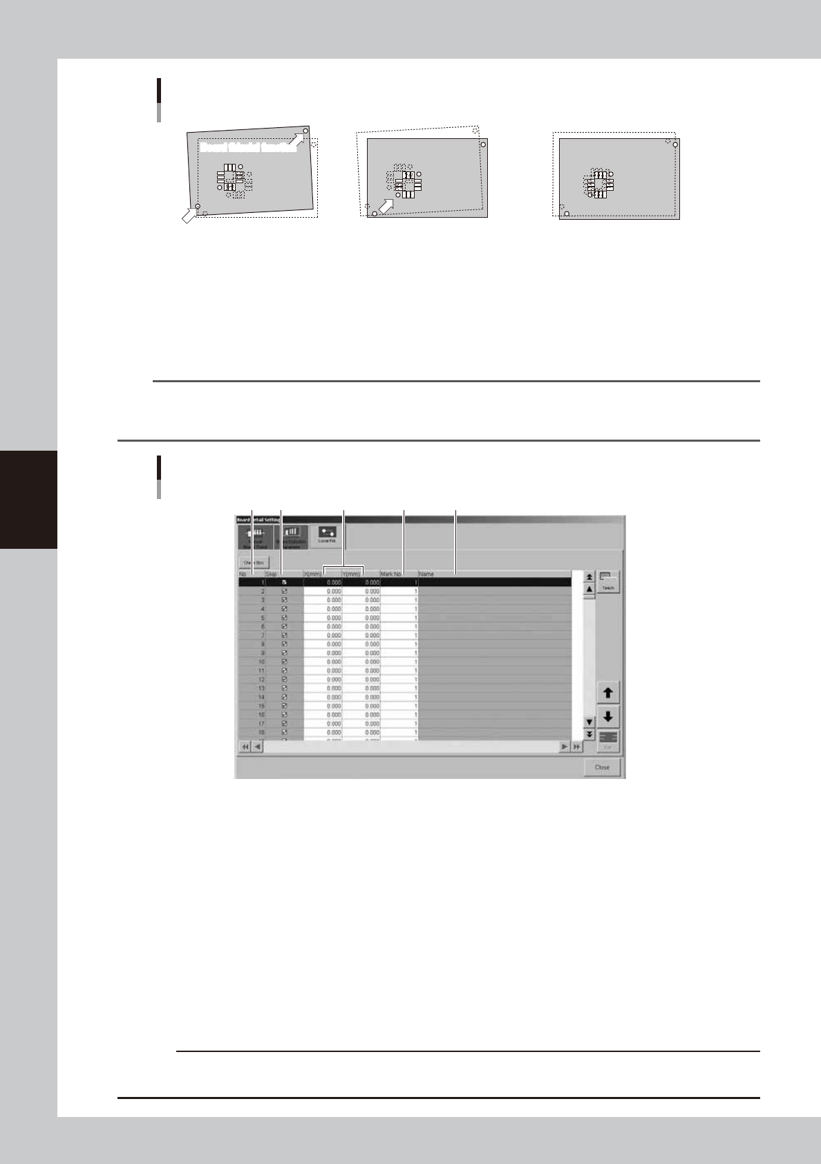
Local fiducial mark setting
1 2 3 4 5
64415-L3-00
1. No.
Shows the local fiducial No.
2. Skip
Sets whether to run or to skip the local fiducial function for the specified No. Clear the check box if running the local
fiducial function.
3. X(mm), Y(mm)
Sets the position for the local fiducial mark position for the specified No. The coordinate reference position is the same
as the board fiducial mark.
4. Mark No.
Specifies the mark No. to use for recognizing the local fiducial mark of the specified No.
5. Name
Shows the name of the mark data specified in the mark No.
c
CAUTION
Always set the board fiducial function to "Use" when using the local fiducial function. The board fiducial function is
disabled if set to "NotUse".