YSP_Users_E.pdf - 第192页
6-8 6 Other functions 1.5 T race T he trace function automatically moves the teac hing unit such as the vision camera to the target position. T his is mainly used to chec k the input XY coordinates and the inspection of …
6-7
6
Other functions
5
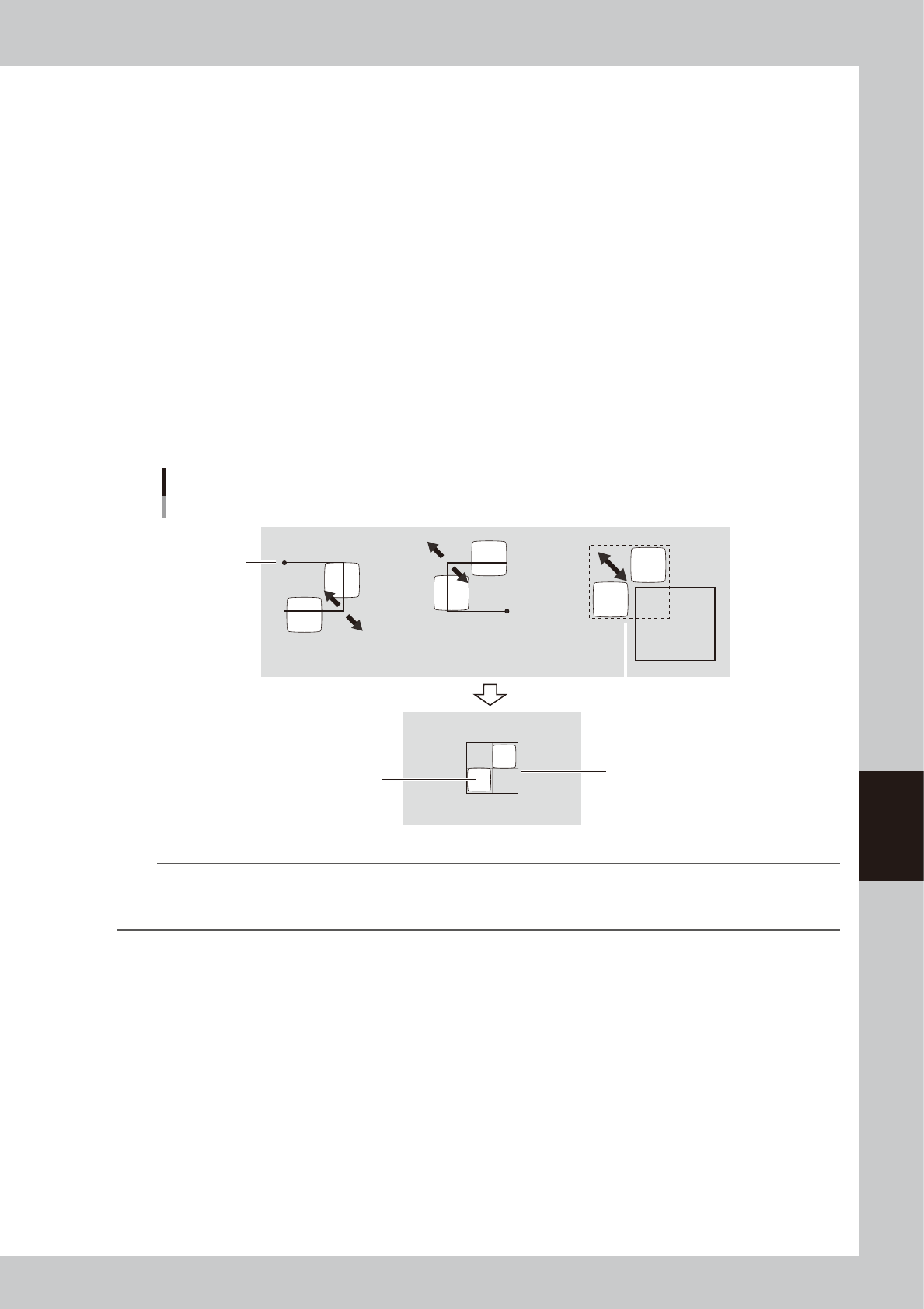
Adjust the cursor teach window.
By using the buttons on the [Cursor] tab, adjust the window size and position to enclose the entire
object. The function of each button is as follows.
[Start] button
Enlarges or reduces the window with the arrow keys, using the lower right corner of the window as a
start point.
[End] button
Enlarges or reduces the window with the arrow keys, using the upper left corner of the window as a start
point.
[Move] button
The entire window moves with the arrow keys.
[Teach] button
Executes teaching.
Arrow buttons
Changes the window size and position according to the movement selected by the [Start], [End] or
[Move] button.
[1 Pixel / 10 Pixel] buttons
Press these buttons to switch the distance that the window moves each time you press an arrow button.
Window size adjustment and movement
Pattern
Enclose the pattern.
Stationary
point
Entire window moves
[End] button [Start] button [Move] button
63602-L3-00
TIP
When you place the mouse pointer in the cursor teach window or on the teach window frame, the mouse pointer
changes to a four-way pointer or two-way pointer, allowing you to adjust the window position and size by dragging
the mouse.
6
Press the [Teach] button.
The center coordinates of the teach window are input as the teaching position.
6-8
6
Other functions
1.5 Trace
The trace function automatically moves the teaching unit such as the vision camera to the target position. This
is mainly used to check the input XY coordinates and the inspection of printed solder and mask apertures.
1
Press the [Teach] button to open the Teach (trace) screen.
A screen identical to the Teach screen appears.
TIP
When you perform trace on a board and the board is not yet clamped on the conveyor, a check dialog box appears
asking you to load a board. Follow the message on the screen to load the board on the conveyor.
When you perform trace on a mask, clamp the mask on the printing table.
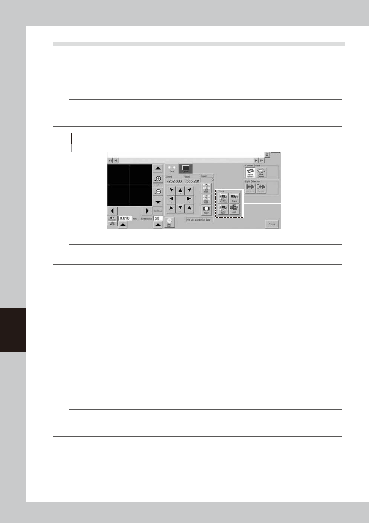
Teach (trace) screen
[Trace] button
64607-L3-00
TIP
The step mode (inching mode) and speed setting are disabled in trace, so they can be any setting values. (Trace
speed is fixed and cannot be changed.)
2
Select the data item for which you want to perform trace.
Line up the cursor with the data line on the upper part of the Teach (trace) screen.
3
Check the surrounding area for safety.
Upon performing trace, the teaching (trace) unit will start to move. Stay out of the axis movement
range.
4
Press the [Trace] button.
The teaching (trace) unit moves to the target position. Use the following trace buttons as needed.
[Trace] button
Performs trace to the selected data.
[Trace Previous] button
Performs trace to the previous data (data one line above).
[Trace Next] button
Performs trace to the previous data (data one line below).
[Auto]
Performs continuous trace automatically towards the end of data lines.
TIP
Visual checks can easily be made using the [Trace Previous], [Trace Next] or [Auto] buttons if inspection coordinates
were entered in the "Teach/Trace" window opened by pressing the [Teach] button under the [Manual Board Check]
or [Manual Mask Check] tab.
(Refer to "3.2 Board data detail setting" and "4.2 Mask data detail setting" in Chapter 4.)
6-9
6
Other functions
2. Pattern matching
Pattern matching is a function for correcting board and mask dimensional errors and positioning errors
occurring from the board clamping mechanism. To use this function, the image of a particular pattern on
the board or mask must be registered as the template. Errors or distortion are corrected by comparing the
registered template with an actual pattern being recognized. Pattern matching is useful when the fiducial
function cannot be used, for example, when there are no fiducial marks on the board or mask, or the mark
does not match any mark recommended by YAMAHA.
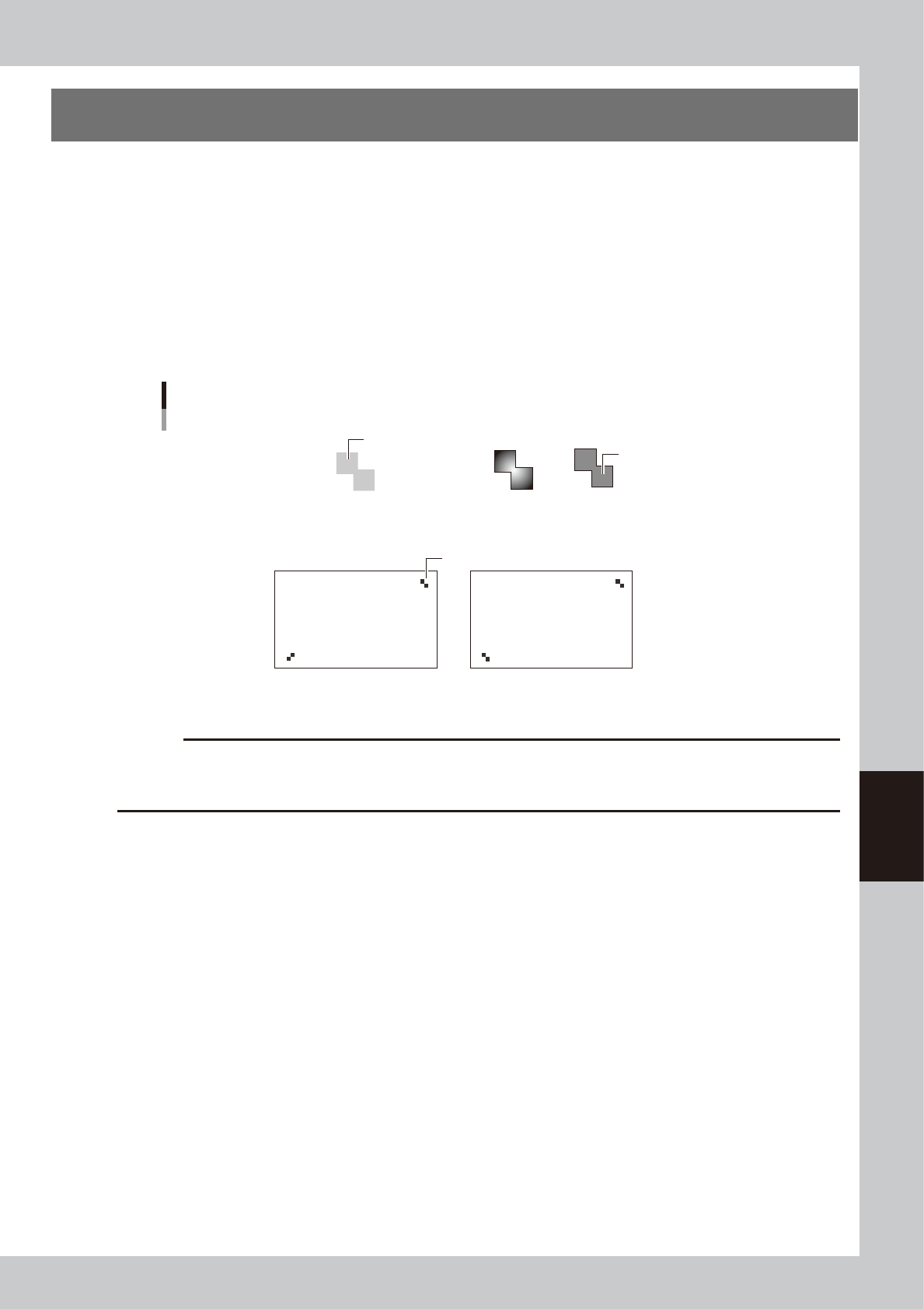
Any shape of pattern can be used as a pattern, but the pattern image size should be smaller than about
1/4th of the vision monitor and must meet the following conditions.
• Each pattern clearly contrasts with the board or mask frame. (Patterns with a definite outline can be used if the contrast
is low.)
• A pair of patterns are diagonally opposing on the board or mask frame. (The same point cannot be used.)
No good
OKOK
OK OK
Pattern conditions
Pattern
Pattern
Board or mask
Board or mask
Low contrast
63603-L3-00
c
CAUTION
Pattern matching requires a longer recognition time than normal mark recognition and its accuracy may drop slightly
compared to cases using circular and square marks. It is not necessary to use pattern matching for marks that can be
correctly recognized with "Algorithm Type" set to "Normal".