YSP_Users_E.pdf - 第254页
A-3 A Appendix 1.2.1 PREVIOUS INTERF ACE connector When the following three conditions are met, the PREVIOUS INTERF A CE circuit in the machine allo ws the next board to be carried in. 1. Machine is read y for carrying i…
A-2
A
Appendix
1.2 Connection between machines
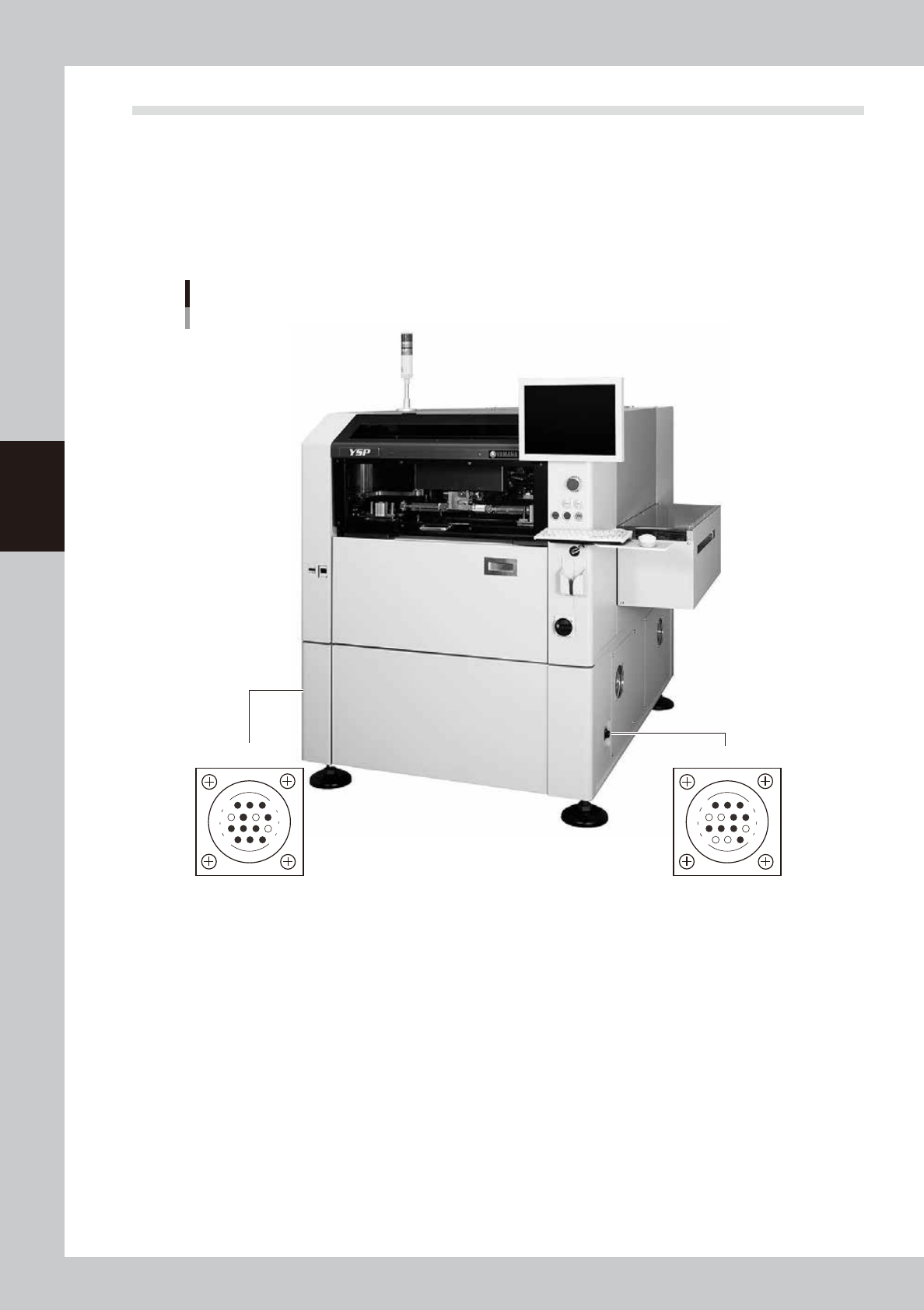
To exchange signals such as board request and operation status with the downstream or upstream machine, the
"NEXT INTERFACE" and "PREVIOUS INTERFACE" connectors located on both sides of the machine are used.
The "NEXT INTERFACE" connector connects to the downstream machine, and the "PREVIOUS INTERFACE"
connector connects to the upstream machine such as a loader. In the case of standard right-to-left flow, the
PREVIOUS INTERFACE connector is located on the right side panel and the NEXT INTERFACE connector on the
left side panel when viewed from the front of the machine. Both connectors use a 14-pin receptacle (AMP
206043-1).
PREVIOUS INTERFACE NEXT INTERFACE
Machine-to-machine interface connectors
Connector : AMP 206043-1 (14-pin receptacle)
14
11
12
7
4
8
3
1
14
11
12
7
4
8
1
3
63005-L3-00
A-3
A
Appendix
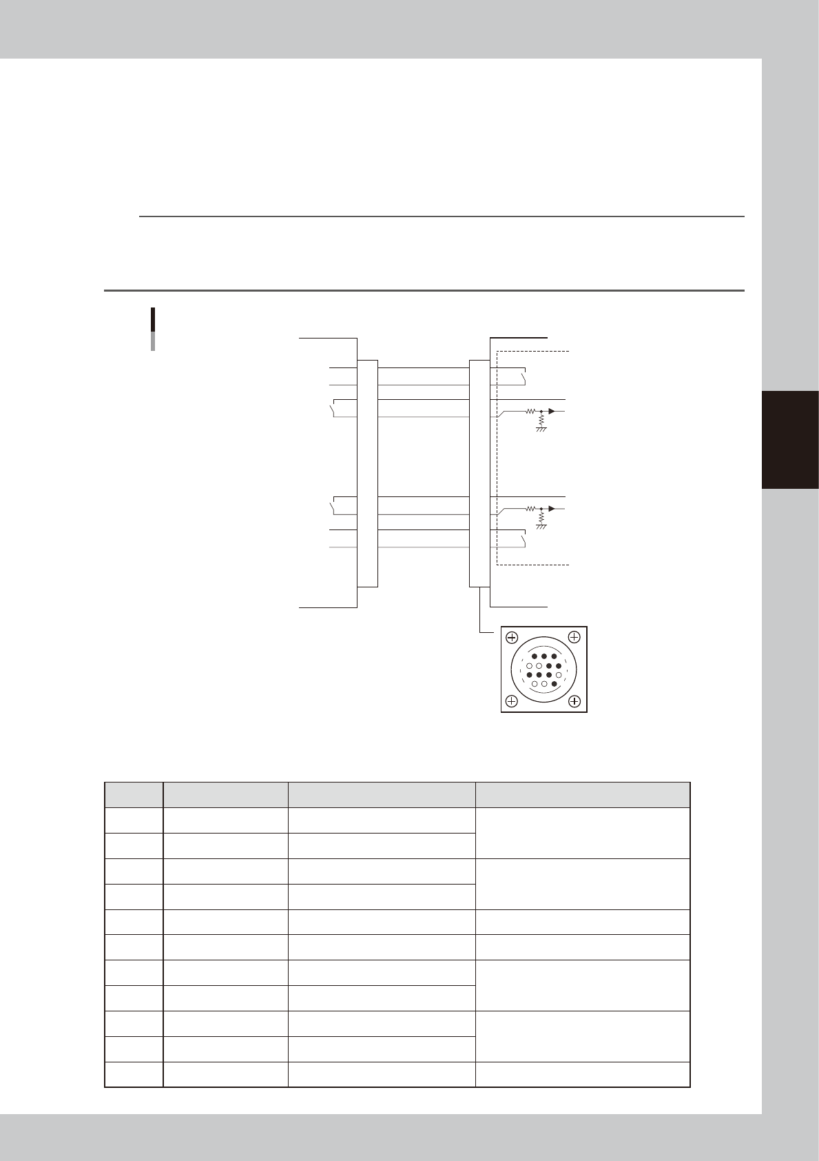
1.2.1 PREVIOUS INTERFACE connector
When the following three conditions are met, the PREVIOUS INTERFACE circuit in the machine allows the next
board to be carried in.
1. Machine is ready for carrying in a board (BUSY OUT: ON)
2. Board carry-in signal is input from the upstream machine. (BA IN [N0108221] : ON)
3. Automatic operation signal is input from the upstream machine. (UR IN [N0108222] : ON)
n
NOTE
• When the automatic operation signal (UR IN) from the loader turns off during transfer of a board, the machine
temporarily stops carrying in the board.
• When the board being carried in is detected by the entrance sensor, the BUSY OUT signal turns off.
• Carrying in the board is finished when both the BUSY OUT and BA IN turn off.
1
2
3
4
5
6
7
8
9
10
11
12
13
14
7
12
4
8
1
14
11
3
BUSY OUT
(T01080E4)
+24V
+24V
LR OUT
(T01080E7)
UR IN
(N0108222)
BA IN
(N0108221)
I/O BOARD
Upstream
This machine
PREVIOUS INTERFACE connector
PREVIOUS INTERFACE circuit
Signal input during board carry-in
Signal output to request board carry-out
Signal output during automatic operation
Signal input during automatic operation
63006-L3-00
n
Board transfer signal specifications
PREVIOUS INTERFACE
Pin No. Signal name I/O specifications Signal specifications
1 BUSY OUT (T01080E4) Relay contact (zero voltage) output Signal output during board carry-in
2 BUSY OUT (T01080E4) Relay contact (zero voltage) output
3 +24V Input common (+24V) Signal input of board carry-out request
4 BA IN (N0108221) Voltage input
5 NC (with dummy pins) (Prevents misinsertion.)
6 to 8 NC
9 +24V Input common (+24V) Signal input during automatic operation
10 UR IN (N0108222) Voltage input
11 LR OUT (T01080E7) Relay contact (zero voltage) output Signal output during automatic operation
12 LR OUT (T01080E7) Relay contact (zero voltage) output
13 to 14 NC
A-4
A
Appendix
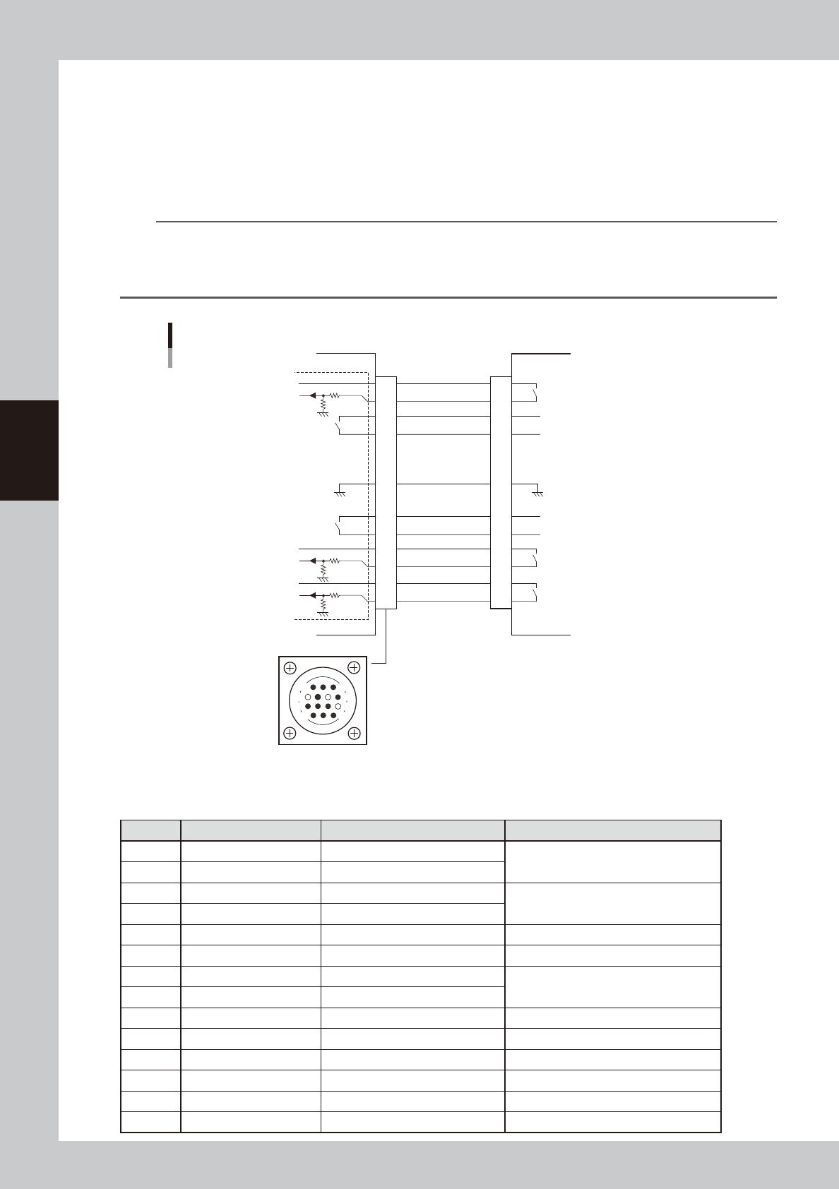
1.2.2 NEXT INTERFACE connector
When the following three conditions are met, the NEXT INTERFACE circuit in the machine allows the board to
be carried out.
1. Machine is ready for carrying out the board (BA OUT: ON)
2. Board carry-in signal is input from the downstream machine. (BUSY IN [N0108220] : ON)
3. Automatic operation signal is input from the downstream machine. (LR IN [N0108223] : ON)
n
NOTE
• When the automatic operation signal (LR IN) from the downstream machine turns off during transfer of a board,
the machine stops temporarily carrying out the PC.
• When the board being carried out is detected by the exit sensor, the BA OUT signal turns off.
• Carrying out the board is finished when both the BUSY IN and BA OUT turn off.
1
2
3
4
5
6
7
8
9
10
11
12
13
14
BUSY IN
(N0108220)
+24V
+24V
UR OUT(T01080E6)
LR IN
(N0108223)
+24V
COUNT RESET
(N0108224)
BA OUT
(T01080E5)
COUNT RESET OUT
I/O BOARD
GND
14
11
12
7
4
8
3
1
NEXT INTERFACE circuit
This machine
NEXT INTERFACE connector
Signal output during board carry-in
Signal input to request board carry-out
Signal input during automatic operation
Signal output during automatic operation
GND
Downstream machine
63007-L3-00
n
Board transfer signal specifications
NEXT INTERFACE
Pin No. Signal name I/O specifications Signal specifications
1 +24V Input common (+24V) Signal input during board carry-in
2 BUSY IN (N0108220) Voltage input
3 BA OUT (T01080E5) Relay contact (zero voltage) output Signal output to request board carry-out
4 BA OUT (T01080E5) Relay contact (zero voltage) output
5 NC
6 NC (with dummy pins) (Prevents misinsertion.)
7 GND
8 NC
9 UR OUT (T01080E6) Relay contact (zero voltage) output Signal output during automatic operation
10 UR OUT (T01080E6) Relay contact (zero voltage) output
11 +24V Input common (+24V) Signal input during automatic operation
12 LR IN (N0108223) Voltage input
13 +24V Input common (+24V) Signal input for COUNT RESET
14
COUNT RESET (N0108224)
Voltage input