YSP_Users_E.pdf - 第258页
A-7 A Appendix 2.2 Mask frame dimensions and mask standard position n Mask frame dimensions and mask standard position Specifications Applicable mask frame size (mm) Mask standard position Standard position offset Settin…
A-6
A
Appendix
2. Compatible masks
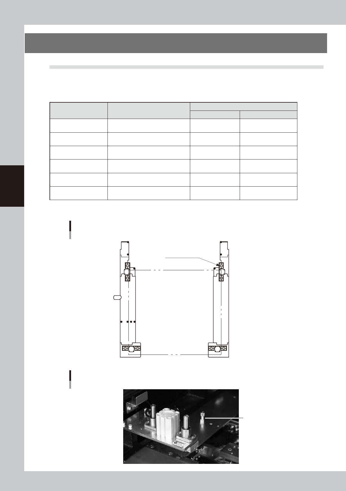
2.1 Mask size and mask stopper pin position
The mask stopper pin position must be changed according to the mask frame size to be used as shown below. One
screw-type mask stopper pin sets the left end position of the mask frame. Screw this stopper pin into one of the "F"
positions when the front conveyor rail is fixed, or one of the "R" positions when the rear conveyor rail is fixed.
n
Mask frame size and stopper pin position
Mask frame size
L (mm) × W(mm)
Applicable board dimensions
L (mm) × W(mm)
Mask frame stopper pin position
L direction W direction
750×750
Board size L50 × W50mm (minimum)
to L510 × W460mm (maximum)
Not used Not used.
750×650
Board size L50 × W50mm (minimum)
to L510 × W460mm (maximum)
Not used 2 (2 locations)
736×736
Board size L50 × W50mm (minimum)
to L510 × W350mm (maximum)
A 1 (2 locations)
650×550
Board size L50 × W50mm (minimum)
to L330 × W250mm (maximum)
B 3 (2 locations)
600×550
Board size L50 × W50mm (minimum)
to L330 × W250mm (maximum)
C Mask adaptor (option)*
550×650
Board size L50 × W50mm (minimum)
to L330 × W250mm (maximum)
D Mask adaptor (option)*
*See "5.1 Using the mask adaptor" in chapter 3 for the mask adaptor (option).
TIP : Store the pins that are not in use.
1
2
1
2
3
A BCD
3
Mask frame size and stopper pin position
Mask frame L
Mask clamp
Mask frame W
63011-L3-10
Mask stopper pin
Mask stopper pin
63012-L3-00
A-7
A
Appendix
2.2 Mask frame dimensions and mask standard position
n
Mask frame dimensions and mask standard position
Specifications
Applicable
mask frame
size (mm)
Mask standard position
Standard
position
offset
Setting X direction
Y direction
A: From outside of mask frame (mm)
B: From center of mask (mm)
X Y
YSP
L736×W736
Center
Center
Center 0 0
Front A 138 B 230 0 0
L650×W550
Center
Center
Center 0 0
Front A 150 B 125 0 0
Panasonic
L600×W550
Center
Center
Center 0 0
Front A 150 B 125 0 0
L550×W650
Center
Center
Center 0 0
Front A 200 B 125 0 0
Minami Kogaku L750×W650
Center
Center
Center 0 0
Front A 150 B 175 0 0
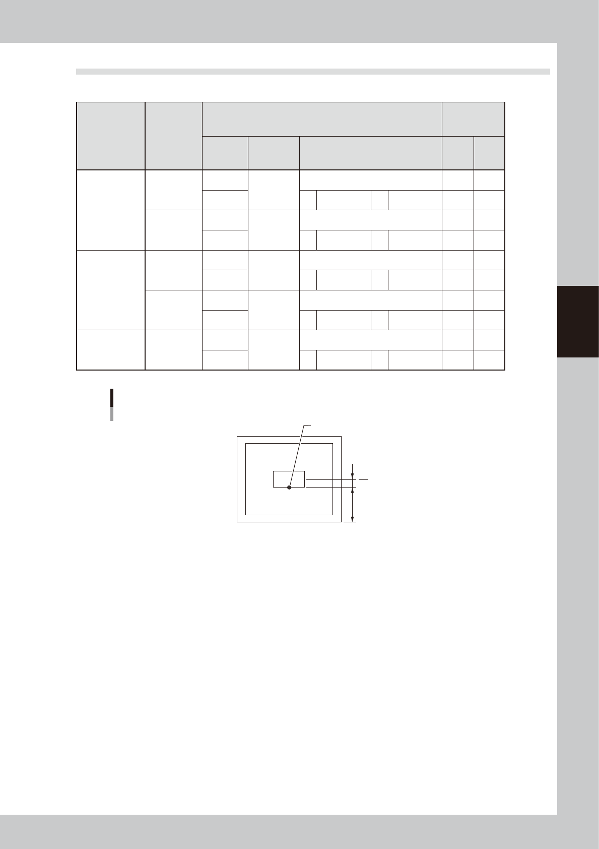
Mask standard position is “Front”.
Mask standard position “Front”
Mask center
A
B
Standard position
63013-L3-00
A-8
A
Appendix
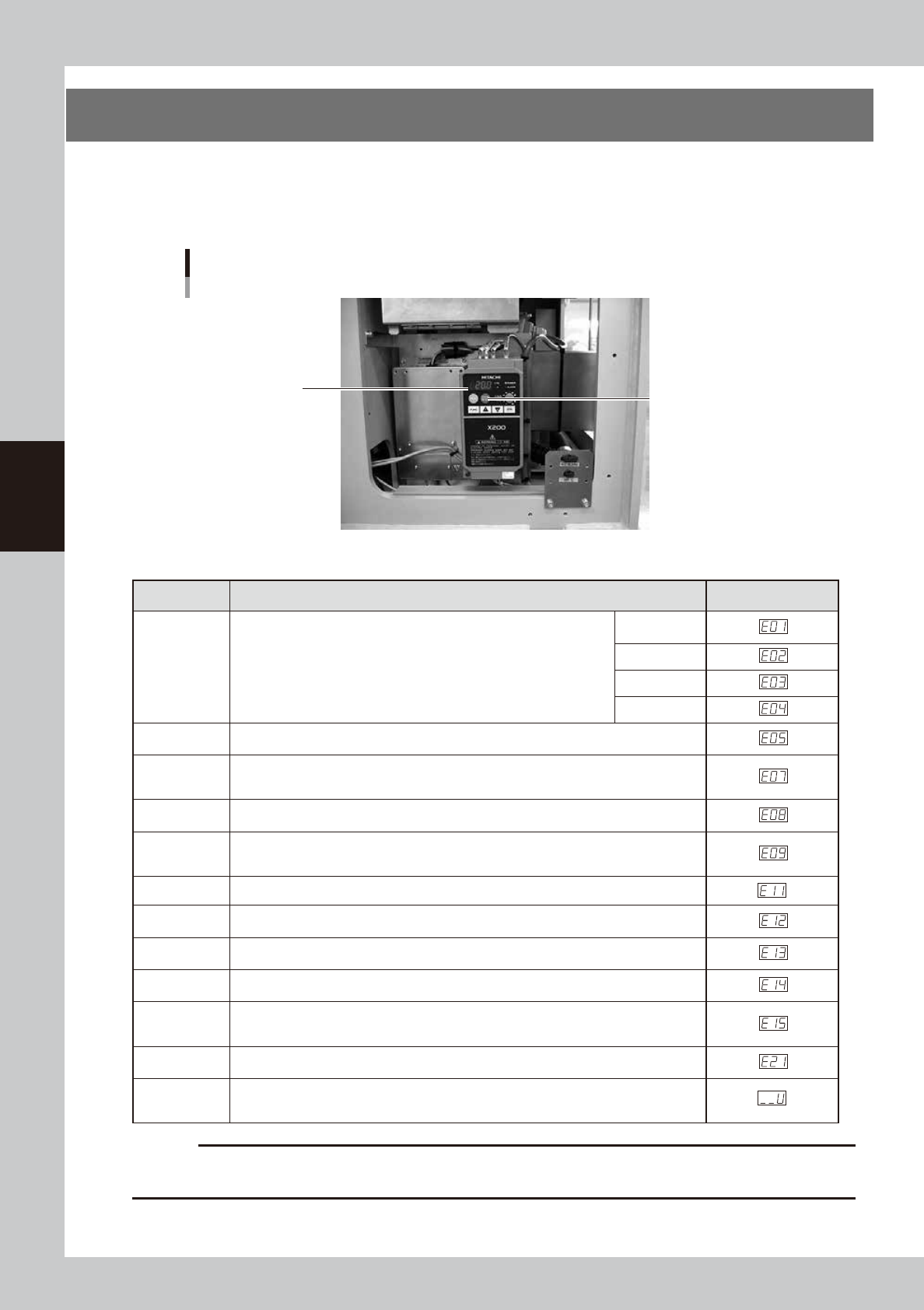
3. Inverter (suction unit)
The suction unit built into the YSP uses an inverter to ensure stable operation.
If a problem occurs with the inverter or suction unit, an error message appears on the YSP operation display.
In this case, check the error number shown on the inverter display panel and contact our sales office or sales
representative.
Inverter
Located behind the right panel on the rear of the machine.
Inverter display panel
Reset button
63014-L3-00
n
Inverter error display
Name Description Error display
Overcurrent
protection
When the motor is restrained or suddenly reduced in speed, a large
current is charged to the inverter, causing a fault. When the inverter
detects 205% peak current of the inverter, an overcurrent occurs.
Constant
speed
Deceleration
Acceleration
Others
Overload
protection
When the inverter output current causes the motor to overload, the electronic thermal
trip in the inverter cuts off the inverter output.
Overvoltage
protection
If regenerative energy from the motor or the main power supply voltage is high,
the protective circuit activates to cut off the inverter output when the voltage of the
converter section exceeds the specification.
EEPROM
error
The inverter output is cut off when EEPROM in the inverter has an error due to external
noise, excessive temperature rise, or other factor.
Undervoltage
protection
When the input voltage received by the inverter decreases, the control circuit does not
function normally. When the input voltage is below the specification, the inverter output
is cut off.
CPU error The inverter output is cut off when the inverter CPU has a malfunction or an error.
External trip
When the external equipment or unit has an error, the inverter receives the
corresponding signal and cuts off the output.
USP error
The USP error is indicated when the power is turned on with the inverter in the RUN
state. (Enabled when the USP function is selected.)
Ground fault
protection
GROUND fault is detected between the inverter output section and the motor when the
power is turned on, to protect the inverter.
Input
overvoltage
protection
When the input voltage is higher than the specified value, it is detected 100 seconds
after power is turned on and the output is cut off.
Temperature
error
When the temperature in the main circuit increases due to cooling fan stop, the inverter
output is cut off. (Only for the model type with cooling fan)
Waiting on
account of
undervoltage
Waiting with the output turned off, because the inverter receiving voltage has dropped.
c
CAUTION
1. Press the reset key 10 seconds after the alarm has occurred.
2. If an EEPROM error occurs, be sure to comfirm the seting value again.